 |
|||
|
|
|||
|
|
|||
| ||||||||||
|
|
 TM 9- 2920- 232- 34&P / TO 38X14- 2- 32
-
-
-
- -
EQUIPMENT DESCRIPTION AND DATA - CONTINUED
-
0002 00
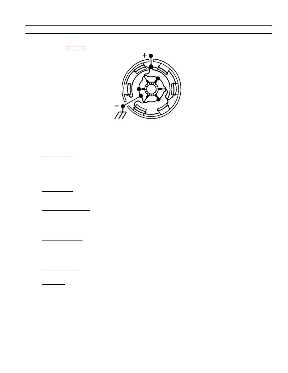
2) Brush holder terminal stud (1) extends through but is insulated from the end plate. This stud is used for
connection to the ground of the power supply as shown schematically in the diagram of internal motor
circuits (fig. 1--3).
3) Each of the remaining brushes (or brush pairs) is in circuit with an assigned pair of series--connected field
windings. Starter, part number 1990272, has one brush and starter, part number 1109972, has two
brushes in each of six brush holders. Refer to paragraph 1--9 for design specifications.
f.
Drive Housing. Drive housing (16) gives support to the bearing at drive--end of the armature shaft and houses
a portion of the drive clutch assembly (19). The drive housing is also the mounting flange for the starter and
has three holes for bolts which attach the starter to an engine. The drive housing has a bolt hole pattern
which permits it to be attached to lever housing (13) with the opening for drive pinion (18) access at anyone of
24 different rotational positions. Only one of these positions is correct for a particular engine application.
Unused holes in this pattern are sealed with spherical rubber plugs.
g. Lever Housing. Lever housing (13) supports the center bearing for the armature, provides a mounting point
for the drive housing, and provides a closure for drive end of the starter frame. It houses the inner portion of
the drive clutch assembly. It supports and houses the shift mechanism.
h. Drive Clutch Assembly. Drive clutch assembly (19) is made up of an overrunning clutch, drive pinion (18), and
a pinion engaging spring. The armature bore of this assembly has a straight spline which allows movement
along the armature shaft, but locks clutch sleeve to armature shaft in rotation. The overrunning clutch is a
seven--roll assembly which allows rotation of the pinion sleeve within the clutch sleeve. Independent rotation
of input or output can occur in one direction only.
Solenoid Assembly. Solenoid relay assembly (8) is a heavy--duty, electro--magnetically actuated switch. It has
i.
stud terminals at one end for connection to a power source and to the motor field winding terminal stud (4). Its
case houses solenoid windings (9) and switch mechanism. The case mounts directly on frame assembly with
four screws. The solenoid has two concentric windings: a pull--in winding and a hold--in winding. There are the
same number of turns in each winding, but the pull--in winding is coarser wire than the hold--in winding.
Solenoid Plunger. Solenoid plunger (10) is the moveable core for the solenoid windings. It attaches to shift
j.
lever (15) and provides for adjustment of pinion clearance.
Shift Lever. Shift lever (15) pivots on a cross shaft supported by lever housing (13). This lever is positioned by
k.
the solenoid acting on solenoid plunger (10) or by plunger spring (12) when solenoid is not energized. The
end of lever opposite that which connects to the plunger is a yoke for pushing drive clutch assembly (19) until
drive pinion (18) is into mesh with the engine starter drive gear.
0002 00- 3
-
|
|
Privacy Statement - Press Release - Copyright Information. - Contact Us |
