 |
|||
|
|
|||
|
|
|||
| ||||||||||
|
|
 TM 9- 2920- 224- 34&P
-
-
-
ASSEMBLY OF THE GENERATOR - CONTINUED
-
0010 00
9. Lead Terminals.
NOTE
Previous alignment of mark on support assembly with
mark on stator housing should put all stator leads in
position to connect only to proper holders.
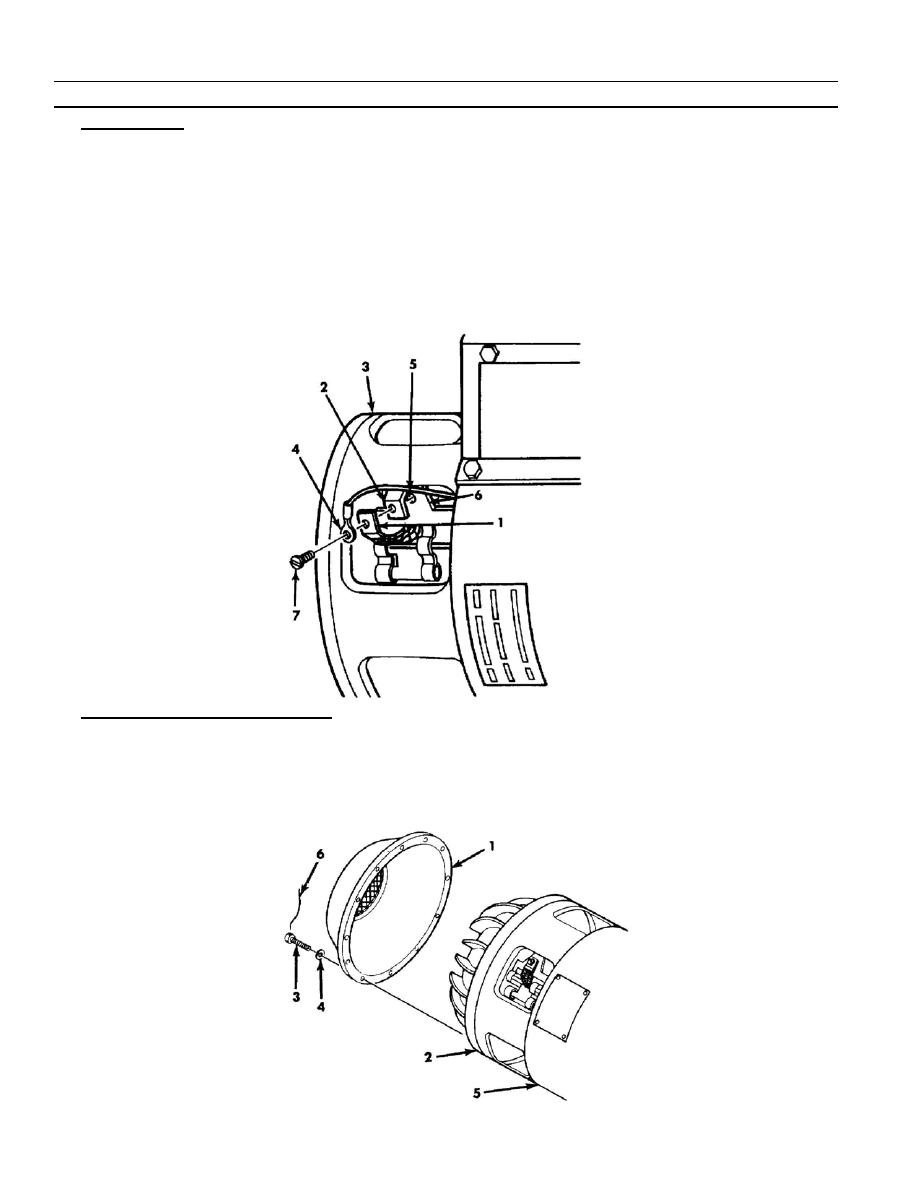
a. Align terminal ends of brush leads (1), of large leads (2) from field coils in stator assembly (3), and of single
small lead (4) from interpole winding in stator assembly with tapped holes (5) in respective electrical contact
holders (6).
b. Connect leads (1), (2), and (4) to respective holders (6) at six places with one machine screw (7) at each
place. Hold terminals (1), (2), and (4) squarely positioned on each holder while tightening screw.
10. Access Cover -- Generator (8717421).
a. On generator (8717421), position impeller access cover (1) on support assembly (2).
b. Install 12 machine screws (3) and 12 flat washers (4). Screw shanks will pass through holes in cover (1)
flange, holes in support assembly (2), and thread into tapped holes in stator housing (5).
c.
Torque all screws (3) to 37--42 Ib--in (4.2 to 4.7 Nm). Install six pieces of nonelectrical wire (6) and tie screws
in pairs.
0010 00- 20
-
|
|
Privacy Statement - Press Release - Copyright Information. - Contact Us |