 |
|||
|
|
|||
|
|
|||
| ||||||||||
|
|
 TM 9- 2920- 224- 34&P
-
-
-
DISASSEMBLY OF THE GENERATOR ASSEMBLY - CONTINUED
-
0008 00
CAUTION
Do not attempt removal of fan motor (69) from fan
housing (60). High speed fan motor could become
misaligned if removal is tried.
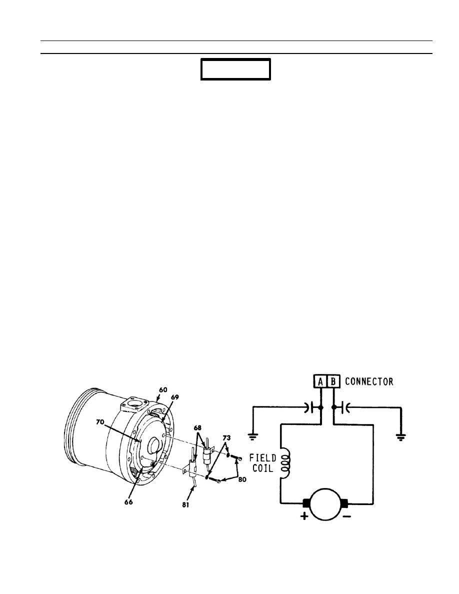
bx. Remove screw (80) and lockwasher (73) from each radio--noise suppression capacitor (68). Discard
lockwasher.
by. Slide insulating sleeve (66) back on wires to expose soldered connections on both radio--noise suppression
capacitors (68).
bz. Note color coding of wires (70) connected to capacitors (68), unsolder connections (81) and remove both
capacitors.
ca. Using capacitor test set and a multimeter, measure through circuit and capacitance of fan motor capacitors,
and capacitors of radio--interference filter. Each capacitor has a through circuit between end terminals. In all
components, measure capacitance between a terminal and the mounting foot.
cb. Fan motor capacitors shall measure 0.25 mfd.
cc. Check dielectric strength of each capacitor with the test set. Replace any capacitor that breaks down under
test.
cd. Perform limited inspection of fan motor commutator and armature bearings. Only the brush track on
commutator can be seen by looking through the holes in fan housing and manually rotating armature. with no
trace of binding. An acceptable commutator surface will be highly burnished and dark copper--colored. If
armature is binding or commutator surface is rough, pitted, scored, burned, or coated with hardened varnish
or carbon, the entire tube axial fan must be replaced.
ce. Using a multimeter set on Rx1 seal e, measure resistance between one motor lead and each brush holder (in
sequence). Measure resistance between the other motor lead and each brush holder (in sequence). The
series of measurements shall show, not necessarily in sequence, two readings of maximum resistance, one
reading of minimum (zero) resistance, and a field resistance of 0.08 to 0.12 ohms with windings at room
temperature.
cf. Inspect insulation of field windings in fan motor for grounds with a multimeter. Resistance measured between
both fan motor leads and metal housing of motor shall be at least one megohm.
END OF TASK
0008 00019/20-bl9nk
0- 08 00 -1a
-
|
|
Privacy Statement - Press Release - Copyright Information. - Contact Us |