 |
|||
|
|
|||
|
Page Title:
Installation of Fuel Injection Pump on Test Stand |
|
||
| ||||||||||
|
|
 TM 9-2910-226-34
and fittings to install pump on the test
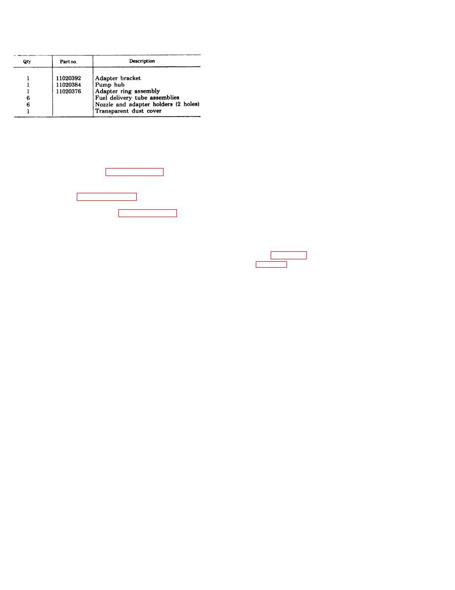
Table 3-3. Typical Test Stand Accessory Kit
stand.
e. Lubricate the test stand rails with test oil and
place the fuel injection pump and bracket on the
rails.
f. Position the fuel injection pump on the test
stand drive coupling allowing a minimum of 1/16
inch clearance between the hubs. Clamp pump
bracket securely in position.
g. Improvise a manifold composed of a 3/8 in.
d. All fuel injection pump assemblies, including
flare tube to in. 45-degree pipe elbow (G, fig. 3-
fuel density compensator where applicable, shall be
163), in. pipe tee (H), in. pipe to in. flared
tested and adjusted on the fuel metering and
tube adapter (J), and in. pipe to in. flare tube
distributing pump test stand prior to assembly on an
adapter (K) (on all pumps except code G). On code G
engine or returning the pump assembly to stock.
pumps only, install improvised adapter manifold
e. Depot overhauled pump assemblies shall be
into hydraulic head inlet fitting after hydraulic head
tested in accordance with paragraphs 3-51, 3-57, and
port closing test, delivery valve test, and hydraulic
3-58.
head leak test.
f. Repaired pump assemblies shall be tested in
3-52. Preparation for Hydraulic Head Tests.
accordance with paragraphs 3-51 through 3-58.
a. Disconnect density compensator overflow line at
g. Pump assemblies removed from engines shall
pump overflow valve.
be tested in accordance with paragraphs 3-51, 3-57,
b. Remove overflow valve and plug openings with
and 3-58 to determine if pump repair is necessary. If
in. and 1/8 in. pipe plugs.
repair is necessary, follow procedures in f above.
c. Remove density compensator to hydraulic head
fuel line.
3-51. Installation of Fuel Injection Pump on Test
d. Position the nozzle tester on the right corner of
Stand. a. Remove the fuel injection pump drive gear
the test stand (fig. 3-164).
and hub (if on pump to be tested).
KEY to fig. 3-163
b. Install adapter ring, Part No. 11020376, on the
fuel injection pump. Torque tighten the three
A
Test stand fuel pressure to supply pump inlet hose
mounting bolts to 27-35 foot-pounds.
B
Supply pump outlet to compensator inlet hose
c. Install fuel injection pump and adapter ring on
C
Compensator inlet tee to pressure gage hose
D
Overflow valve to test stand fuel return hose
the test stand adapter bracket, Part No. 11020392.
Test stand lube pressure to fuel injection pump hose
E
Torque tighten the four mounting bolts to 27-35
Fuel injection pump lube return to test stand lube
F
foot-pounds.
return hose
d. Lubricate the adapter ring oil seal and install
Elbow, 45-degree, 3/8 inch flare tube to 1/4 inch
G
pipe
the test stand pump hub, Part No. 11020384, and
H
Tee, 1/4 inch pipe
Woodruff key on the injection pump shaft and secure
Adapter, 1/4 inch pipe to 1 /2 inch flare tube
J
with retaining nut and lockwasher. Torque tighten
K
Adapter, 1/4 inch pipe to 1/4 inch flare tube
nut to 65-70 foot-pounds.
NOTE
Do not remove any elbows or fittings from
the pump. Fabricate necessary connections
3-94
|
|
Privacy Statement - Press Release - Copyright Information. - Contact Us |
