 |
|||
|
|
|||
|
Page Title:
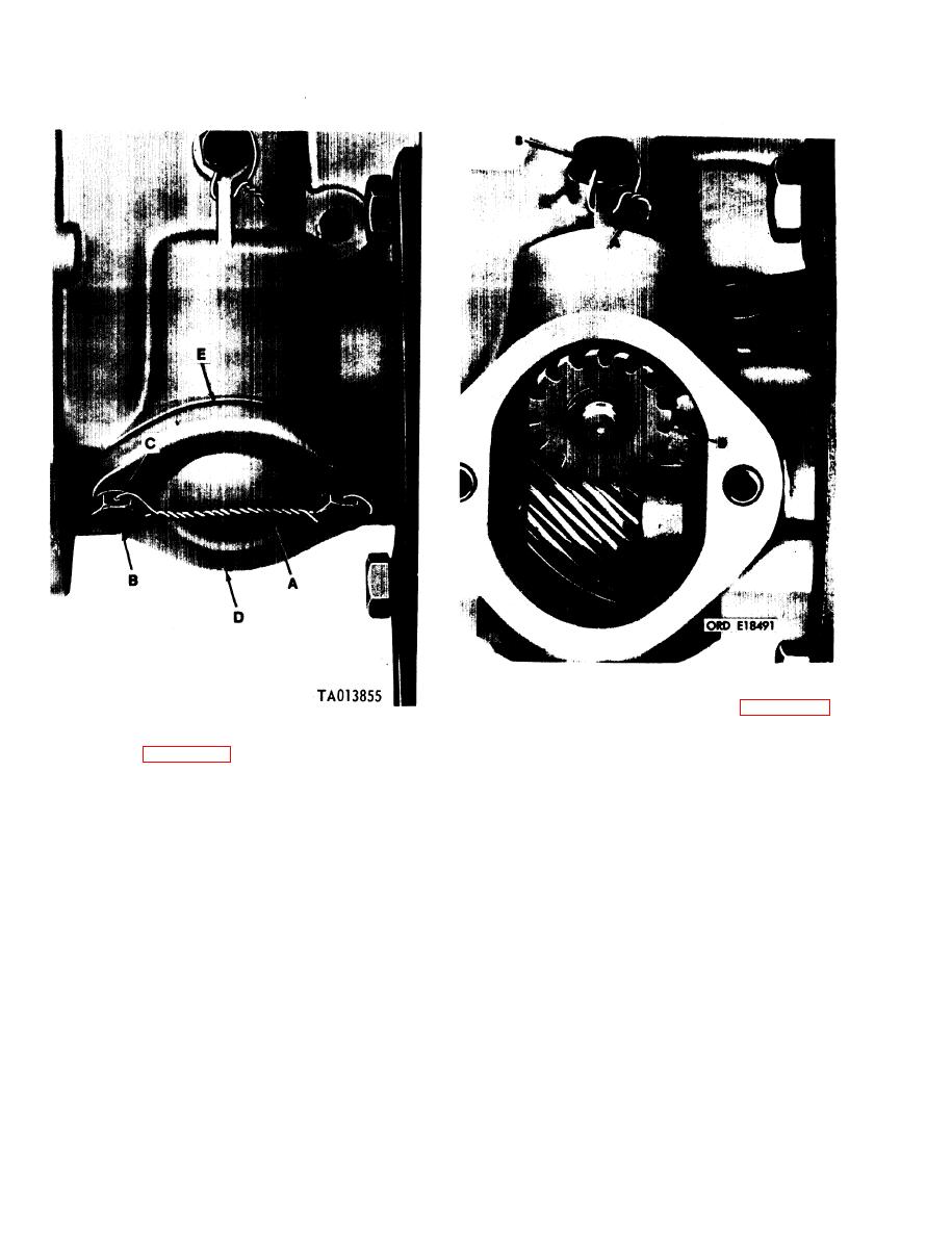
Figure 3-25. Removing quill shaft pad cover. |
|
||
| ||||||||||
|
|
 TM 9-2910-226-34
Figure 3-26. Removing quill shaft assembly.
Straighten tabs on lockwashers (A) and remove four
Figure 3-25. Removing quill shaft pad cover.
machine screws and lockwashers (B). Remove
bearing retaining plate (C). Remove pump housing
remove machine screw (B) and copper gasket (C).
from holding fixture.
Discard copper gasket. Remove quill shaft assembly
(D).
3-10
|
|
Privacy Statement - Press Release - Copyright Information. - Contact Us |
