 |
|||
|
|
|||
|
Page Title:
Fuel Supply Pump Assembly (Code A and Early Code F Injection Pumps). |
|
||
| ||||||||||
|
|
 TM 9-2910-226-34
b. The governor housing (TT) is attached to the
of the injection pump housing (AC). The main
components of the governor are the governor weight
and spider assembly (UU, WW), sliding sleeve (VV),
governor inner and outer springs (RR, SS), fulcrum
lever (NN), and operating linkage.
c. The governor weight and spider assembly is
pressed on an extension of the camshift (ZZ) and
contains two movable governor weights (UU) which
are pinned on opposite sides of friction drive spider
(WW). The weights swing freely on their pins.
d. The sliding sleeve moves freely on the cam-
shaft and contains a thrust bearing against which
the weight fingers bear. Each side of the sliding
sleeve contains a slot to receive the pivot pins of the
fulcrum lever. Counterbores at the rear of the sliding
sleeve receive the governor inner and outer springs.
e. The smoke limit cam (MM) is located at the top
of the fulcrum lever (NN) and rides on the stop plate
(PP) of the density compensator. The operating lever
shaft (E, fig. 1-19 and 1-20). The operating shaft is
connected to the fulcrum lever by suitable linkage.
A Fuel control rod
F Operating lever
B Torque link spring
G Operating shaft spring
C Fulcrum lever
H Torque link
D Shaft spring plate
J Fulcrum lever pivot pin
E Operating shaft
K Yoke pivot pin
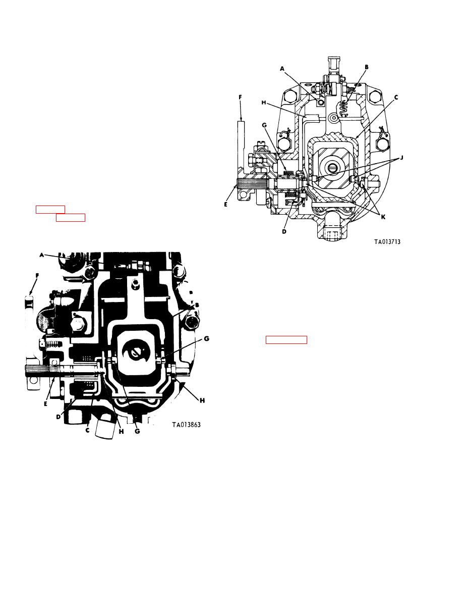
Figure 1-20. Governor assembly (code A), rear sectional view.
1-14. Fuel Supply Pump Assembly (Code A and
Early Code F Injection Pumps).
NOTE
The key letters shown below in parenthesis
refer to figure 1-21.
a. The fuel supply pump assembly consists of the
supply pump housing (B), camshaft driven gear (C),
drive shaft (D), idler gear (E), housing cover (A),
and check valve (G).
b. The supply pump housing contains inlet and
outlet ports for the flow of fuel. It also houses the
check valve which is held in place by the check valve
spring (F) and valve screw- (H). -
c. The housing cover and cavity in the supply
pump housing form a compartment in which the idler
gear and drive shaft rotate, The cover also houses
the relief valve (J) and spring (K).
d. Rotation is imparted by the fuel pump cam-
A Fuel control rod
E Operating shaft
shaft driven gear (C).
F Operating lever
B Fulcrum lever
G Fulcrum lever pivot pin
C Shaft spring plate
H Yoke pivot pin
D Operating shaft spring
Figure 1-19. Governor assembly {code B, C, D, E, F and G),
rear sectional view.
1-22
|
|
Privacy Statement - Press Release - Copyright Information. - Contact Us |
