 |
|||
|
|
|||
|
Page Title:
Fuel Shutoff Rod Assembly or Solenoid Assembly |
|
||
| ||||||||||
|
|
 TM 9-2910-226-34
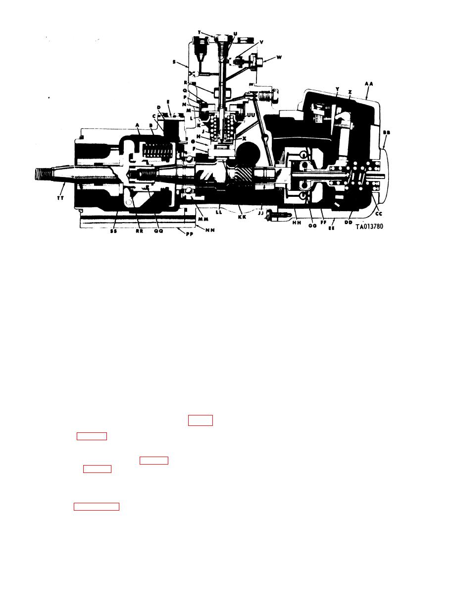
Sliding gear
A
Y
Stop plate
Timing device spring
B
Smoke limit cam
Z
Timing device hub
C
Governor cover
AA
Timing pointer
D
Governor end cap
BB
Timing cover
E
Governor inner spring
CC
Tappet roller pin
F
Governor outer spring
DD
Tappet guide
G
Governor housing
EE
Spring lower seat
H
Governor weight
FF
Plunger lock
J
Sliding sleeve
CC
Plunger inner spring
K
Friction drive spider
HH
Spring upper seat
L
Camshaft bushing-type bearing
JJ
Plunger guide
M
Tappet roller
KK
Drive gear retainer
N
Camshaft
LL
P
Plunger drive gear
Camshaft ball bearing
MM
Q
Gear thrust washer
Injection pump housing
NN
R
Plunger sleeve
Timing device housing
PP
Hydraulic head
S
End play spacer
QQ
Plunger bore screw
T
RR Sliding gear spacer
Fuel plunger
SS Spider thrust plate
U
TT Weight and spider assembly
V
Fuel delivery valve
UU Outer plunger spring
Delivery valve screw
W
Plunger button
X
Figure 1-14. Metering and (distributing fuel injection pump assembly (code G), left sectional view.
a. The hydraulic head assembly consists of the
1-7. Fuel Shutoff Rod Assembly or Solenoid
hydraulic head (S), fuel plunger (U), plunger sleeve
13) or timing window cover solenoid shutoff
(R), plunger drive gear (P), fuel delivery valve (V),
assembly (E, fig. 1-13) is attached at the hydraulic
plunger inner spring (K), and other related parts.
head timing window. When the fuel shutoff rod is
b. The hydraulic head has a centrally ground and
pulled to the rear, or the solenoid is actuated, it
lapped bore into which the fuel plunger fits. It is
engages the fuel control unit (B, fig. 1-13) or the fuel
counterbored and threaded at the upper end for the
control unit (B, fig. 1-13), and shuts off the fuel.
plunger bore screw (T). Six discharge passages
1-8. Hydraulic Head Assembly.
extend symmetrically from the plunger bore and
meet six vertical outlet passages. The fuel delivery
NOTE
valve is located in the head and held by a spring and
The key letters shown below in parentheses
the delivery valve screw (W). A passage from the
refer to figures 1-14, 1-15, 1-16, and 1-17.
1-16
|
|
Privacy Statement - Press Release - Copyright Information. - Contact Us |
