 |
|||
|
|
|||
|
|
|||
| ||||||||||
|
|
 TM 9-2835-255-34
INLET GUIDE VANE (IGV) POWER TRANSFORMER REPLACEMENT (Sheet 3 of 5)
NOTE
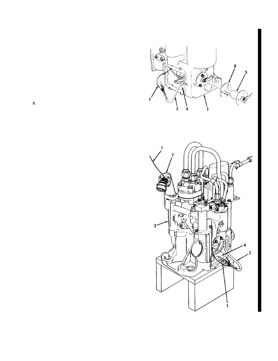
IDo not pull nonelectrical wire (1) out of electro-
mechanical fuel system. Keep wire routed for
installation.
7.
PULL THE POWER TRANSFORMER WIRE
(RED) (2) OUT OF THE
ELE:CTROMECHANICAL FUE.L SYSTEM
(3) THROUGH THE ACCESS CAVITY (4).
REMOVE TAPE AND DISCONNECT
NONELECTRICAL WIRE FROM PINS.
9.
REMOVE POWER TRANSFORMER (5)
AND GASKET (6).
NOTE
If wires other than the wires you work on break or
come out of the housing. assemble electro-
mechanicial f'uel system using old part and replace
electromecharnical tuel syslem.
10. INSPECT WASHERS FOR DAMAGE.
REPLACE AS REQUIRED.
"
~
INSTALLATION:
1.
INSTALL NEW GASKET (6) AND NEW
POWER TRANSFORMER (5) ONTO ELEC-
TROMECHANICAL FUEL SYSTEM (3).
NOTE
Do not put in new screws and washers in power
translomer at this time.
2
2
ATTACI-l NONELECTRICAL WIRE (I) TO
PINS AND ROUTE THROUGH ELECTRO-
MECHANICAL FUEL SYSTEM (4).
a At access cavity (4), attach non- electrical
wire ( 1 ) to pins with knot. Cover with tape
t0 form smooth surface.
b. Route power trarnsforner wire (2) carefully
out through. connector elbow (7).
c. Remove Iape and nonelectrical wire from
pins.
Go on to Sheet 4
Change 4 7-37
|
|
Privacy Statement - Press Release - Copyright Information. - Contact Us |