 |
|||
|
|
|||
|
|
|||
| ||||||||||
|
|
 TM 9-2835-255-34
NO. 12 BEARING AND SPLINED COUPLING REPLACEMENT (Sheet 7 of 7)
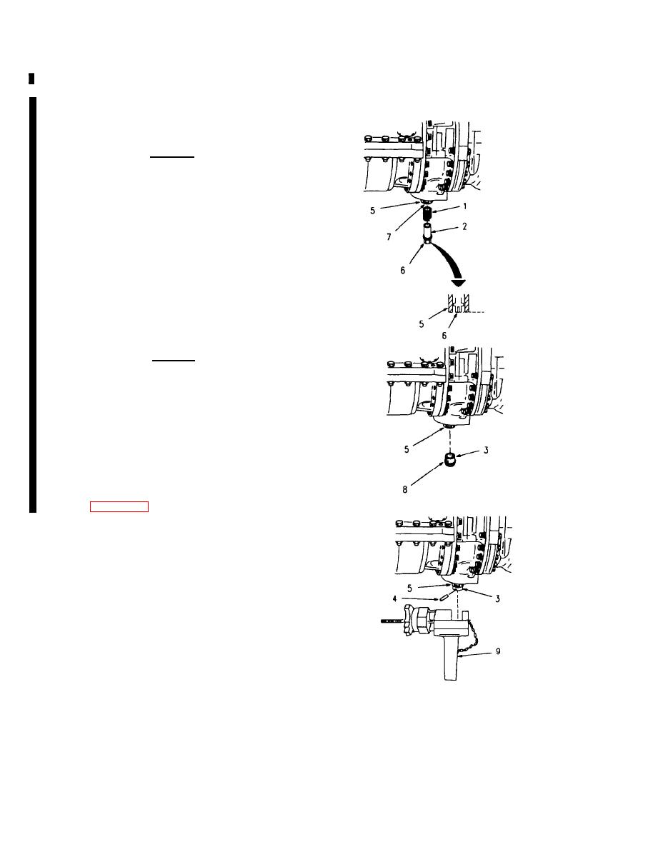
4. INSTALL SPRING (1) SPRING RETAINER (2)
DUST CAP (3) AND SPRING PIN (4) IN SPLINED
COUPLING (5).
CAUTION
Do not screw spring retainer (2) in beyond
end of splined coupling (5) and then
unscrew to set flushness. Damage to parts
may result.
a.
Install spring (1), into splined coupling (5).
Screw spring retainer (2) into coupling (5) until
end of retainer (2) is just flush with end of cou-
pling (5); then line up slot (6) in retainer (2)
with closest hole (7) in coupling (5).
b.
Line up holes (8) in dust cap (3) with holes in
coupling (5), and install dust cap (3).
CAUTION
Spring pin must be installed so that both
ends of pin do not stick out into coupling
splines to prevent damage to parts.
c.
Using driver (9). put spring pin (4) into driver
(9), then install pin (4) into hole in coupling (5)
and dust cap (3), so that both ends of pin (4)
are within splines.
5. INSTALL ACCESSORY GEARBOX MODULE ON
ENGINE (PAGE 7-12).
LE5527
End of Task
5-130
Change 6
|
|
Privacy Statement - Press Release - Copyright Information. - Contact Us |