 |
|||
|
|
|||
|
|
|||
| ||||||||||
|
|
 TM 9-2815-224-34&P
Engine Tune-Up Instructions (Cont)
FUEL MODULATOR ADJUSTMENT.
This task covers:
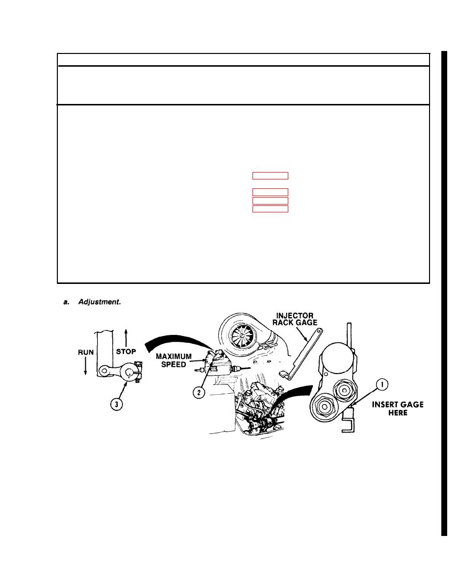
a. Adjustment
b. Follow-on Maintenance
INITIAL SETUP
Models
References
All
None
Test Equipment
Equipment Condition
Condition Description
TM or Para
None
TM 9-2320-279-20 Air intake ducting removed.
Special Tools
Injector rack control levers
Gage, injector rack, J34080
adjusted.
Throttle air cylinder removed.
Fabricated Tools
Spring housing removed.
Gage, feeler, 0.004 in. (0.102 mm)
Engine speed adjusted.
Gage, feeler, 0.005 in. (0.127 mm)
Special Environmental Conditions
Gage, feeler, 0.017 in. (0.432 mm)
None
Supplies
General Safety Instructions
None
None
Personnrl Required
Level of Maintenance
MOS 63W, Wheel vehicle repairer
Direct Support
NOTE
Use the injector next to and forward of the fuel modulator assembly.
(1)
Insert injector rack gage on injector control rack (1) so that handle is at approximately 45 degree
angle.
(2)
Position governor lever (2) toward maximum speed position and run/stop lever (3) in run
position. The injector rack gage must stand up while being held in place by the rack.
Change 2
|
|
Privacy Statement - Press Release - Copyright Information. - Contact Us |
