 |
|||
|
|
|||
|
|
|||
| ||||||||||
|
|
 INJECTION
FUEL
NOTE
Pump Standard and
Oversize Buttons
Button size is determined by code number or let-
ter stamped on its side. See table for button size.
Size
Determine correct button thickness before in-
(thickness
Code
stalling new pump.
in inches)
No.
Letter
Part Number
Inspect button for evidence of excessive wear
damage.
F
1
A
147-0147
0.119
defective, replace with button of same size.
147-0149
0.113
3
c
0.095
147-0154
8
J
Add port closing (PC) dimensions and button thickness of
G
147-0161
0.104
11
STD, or no
old pump.
mark
0.122
147-0190
12
M
Subtract PC dimensions of new pump from total in step G.
H
0.131
15
147-018'7
R
0.134
16
147-0186
s
I
Select button with thickness closest to number obtained in
step H.
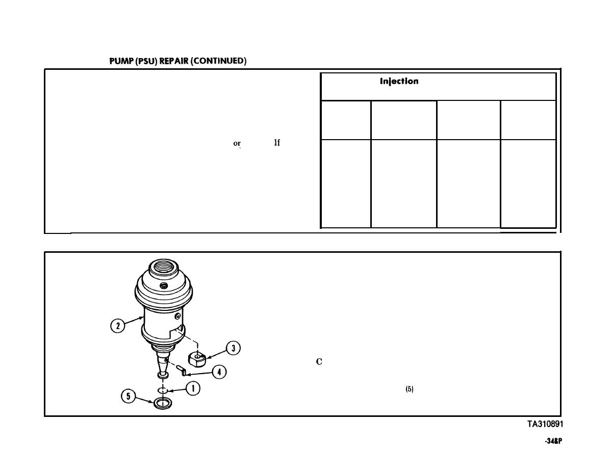
ASSEMBLY
Install spring ring (1) on plunger end of hydraulic head
A
assembly (2).
Insert plunger sleeve (3) into head assembly (2) with iden-
B
tification dot on sleeve (3) facing upward and located at
right-hand side of head (2).
Install drive pin (4) with long end of pin head pointing down
and away from head assembly (2).
Place thrust washer
on head assembly (2).
D
TM 9-2815-221
|
|
Privacy Statement - Press Release - Copyright Information. - Contact Us |