 |
|||
|
|
|||
|
Page Title:
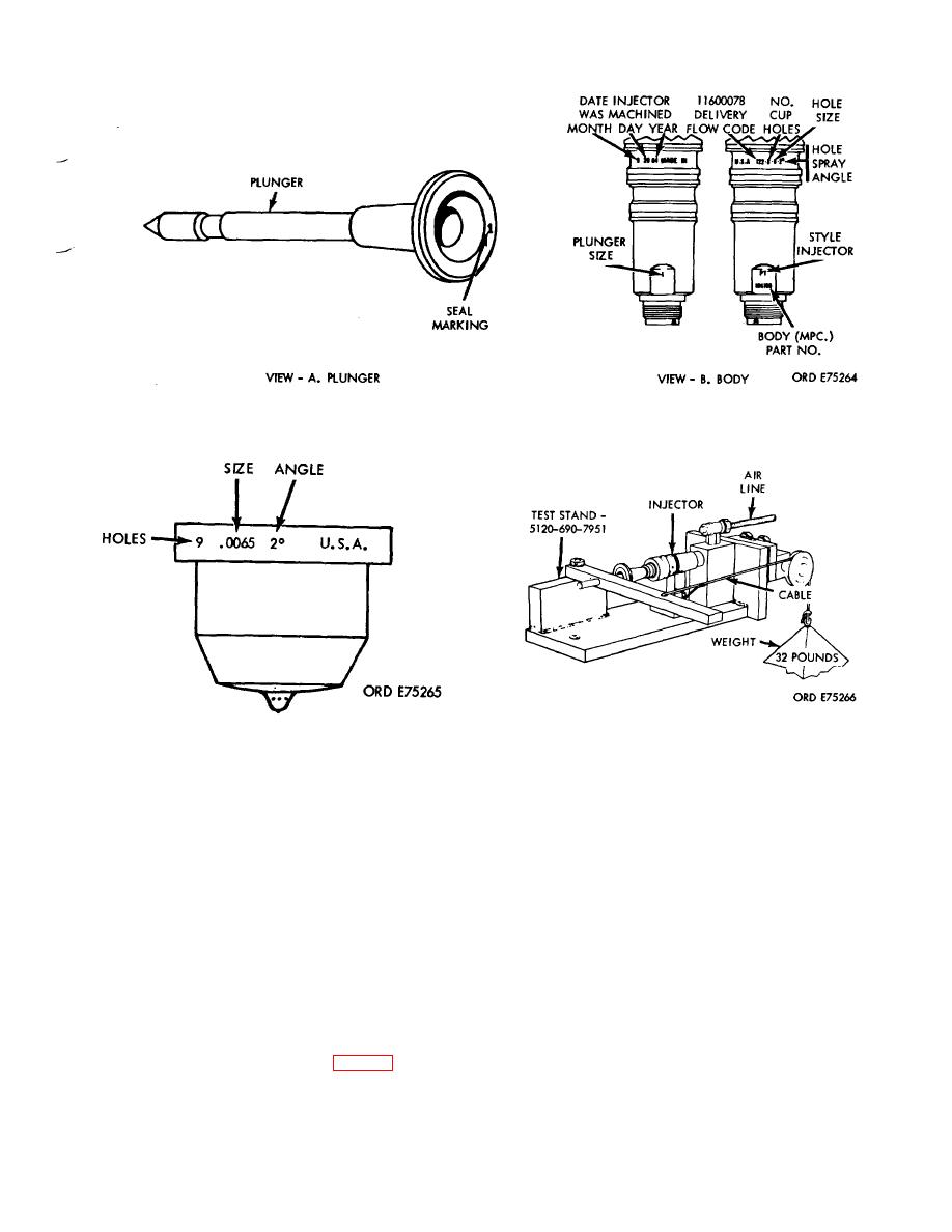
Figure 3-56. Injector body and plunger markings. |
|
||
| ||||||||||
|
|
 *TM 9-2815-213-34
Figure 3-56. Injector body and plunger markings.
Figure 3-58. Injector plunger seat test.
Figure 3-57. Injector cup marking.
10) If the cup seat is damaged in any way and
tors.
It flow tests the complete injector assembly by
injector does not pass cup-to-plunger seat test,
measuring fuel delivery. The injector is actuated under
plunger may be lapped into cup to obtain good
controlled conditions closely simulating actual operating
seating. Use no greater than 300 grade lap- ping
conditions. The test stand counts injection strokes, supplying
compound mixed with OE30 lubricating oil. Applying
fuel at specified pressure, and measures the delivery in a
light pressure, oscillate plunger in cup back and forth
glass graduate.
The following preliminary steps and
for approximately one minute.
procedures are required prior to test stand operation.
CAUTION
CAUTION
Before operating the test stand make sure that the
After lapping, both the cup and plunger must
cam box is filled to the level of the sight glass with
be thoroughly cleaned. Lapping compound
OES-30 oil.
will damage fuel system unless removed.
The most effective cleaning process is the
NOTE
use of an ultrasonic cleaner, if available, and
an after rinse in fuel oil.
The test stand must be located near hot and cold
(11) If injector is satisfactory, remove
water connections. Water temperature, controlled by
plunger. Re-install spring and plunger.
a mixing valve, is used to maintain test fuel at an
80/100 degree Fahrenheit temperature
The injector test stand is used to test all injec.
range.
3-27
|
|
Privacy Statement - Press Release - Copyright Information. - Contact Us |