 |
|||
|
|
|||
|
|
|||
| ||||||||||
|
|
 **TM 9-2815-213-34
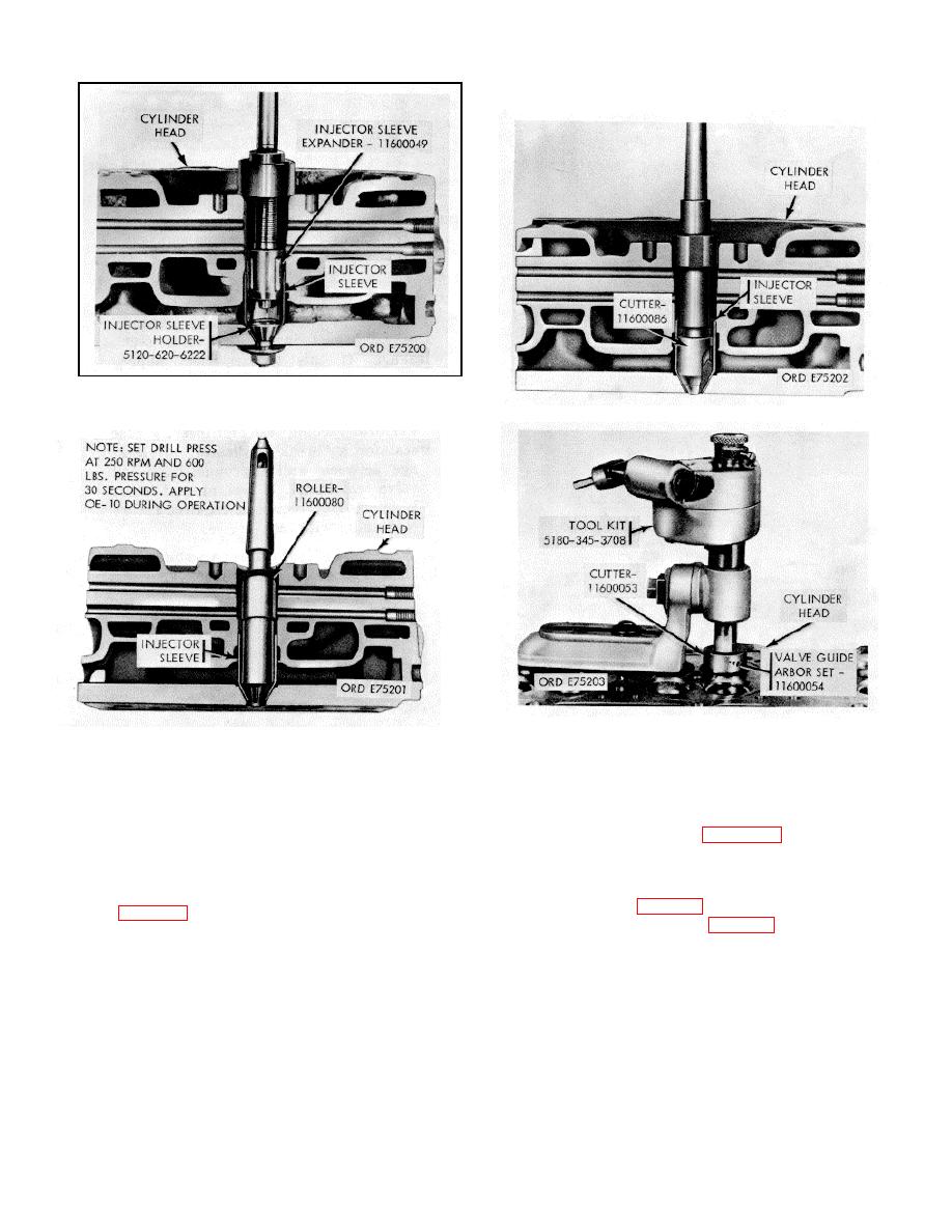
Figure 3-43. Injector sleeve seat cutting.
Figure 3-41. Injector sleeve rolling-upper portion.
Figure 3-44. Valve seat insert counterbore.
Figure 3-42. Injector sleeve rolling-lower portion
must be a perfect fit on pilot mandrel.
and proper size mandrels to fit reamed valve guides.
(b) Run out should not exceed 0.002 inch total
Dress grinding stone to 30 degrees from horizontal.
indicator reading.
(2) Grind valve seats, holding motor as
Valve Assemblies. Reassemble valve assemblies
f.
nearly vertical as possible.
in reverse order of disassembly (para. 3-64).
(3) Check valve seat width which should
be 1/16 to / inch.
3-69. Tests
(a) If ground seat is wider than 1/8
inch maximum stock can be removed from points "A"
and "B" (fig. 3-29) with specially dressed valve seat
leaks with cylinder head gage (2, fig. B-29) as follows:
grinder stones.
(b) Narrowing should not extend beyond
CAUTION
chamfer on seat insert. Chamfer provides for peen
metal.
Never vacuum test cylinder head with injector
(4) Dress wheel for final finish and finish
installed.
Installation of injectors could cause
grind with light touches of stone against valve seat
misalignment of valves in valve seat area and result
face.
in leakage during test.
(5) Check valve seat concentricity with valve
seat indicator.
(1) Select a vacuum cup of proper size for
(a) Use valve guide as a center. Gage
valve to be tested.
3-21
|
|
Privacy Statement - Press Release - Copyright Information. - Contact Us |