 |
|||
|
|
|||
|
|
|||
| ||||||||||
|
|
 *TM 9-2815-213-34
a. Using a suitable hoisting device, (i.e., over-head
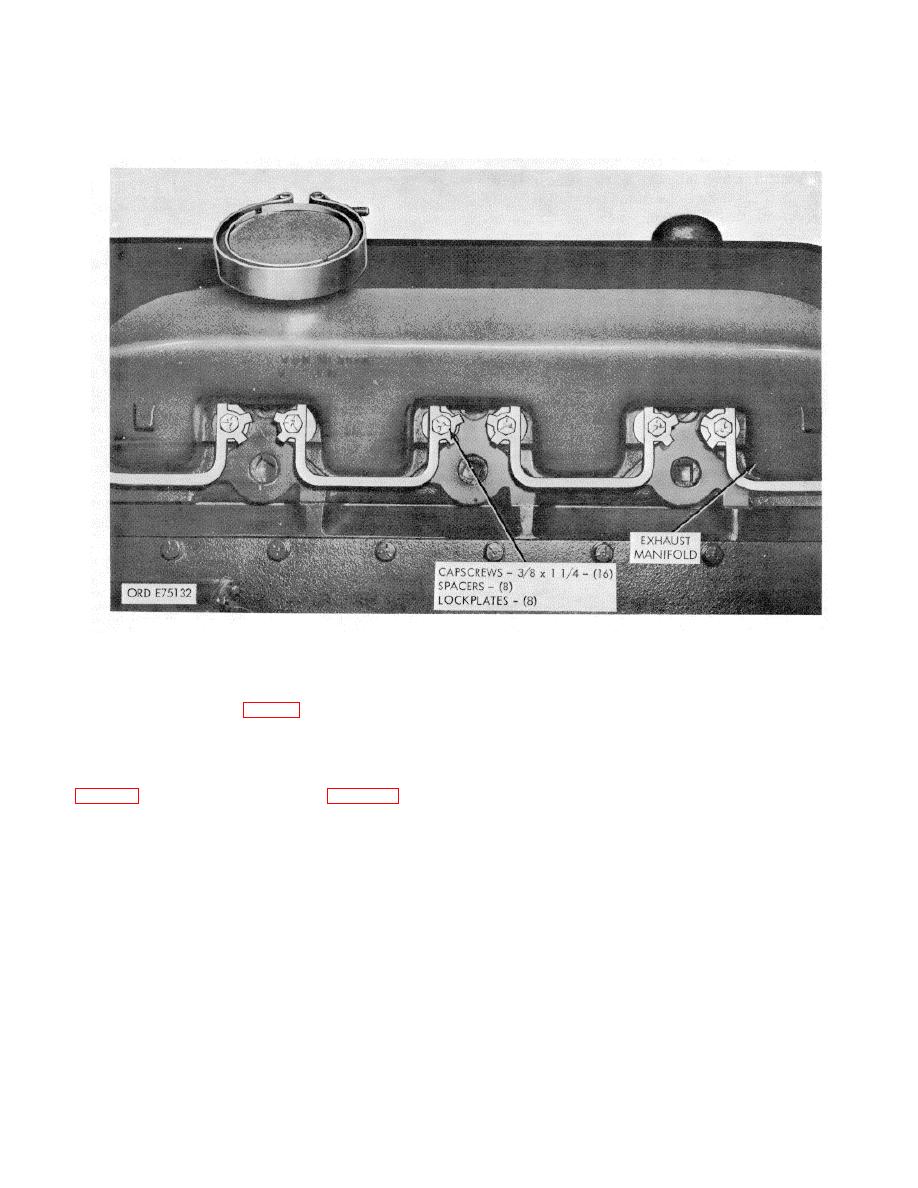
b. Remove eight capscrews, spacers, and four
chain fall, A frame hoist, or gooseneck hoist), attach
lockplates, securing left bank exhaust manifold to head.
lifting hooks to engine front and rear lifting eyes, (figs. 1-
c. Remove manifold and four manifold to block
1 and 1-2) and raise engine.
gaskets (fig. 21).
Figure 2-1. Exhaust mainifold--removal/installation.
d. Remove 13 capscrews and lockwashers
(3) Remove two capscrews, and lockwashers
securing oil cooler to engine (fig. 2-2).
securing alternator to mounting bracket and remove
e. Remove oil cooler and four gaskets.
f. Remove 12 capscrews, lockwashers, and one
(4) Remove four capscrews, lockwashers, and flat
gasket, securing cover plate to block and remove plate.
washers securing mounting bracket to intake manifold.
g. Install engine rebuild stand and adapter (26 and
(5) Remove capscrew and lockwasher securing fan
27, fig. B-28) to engine block as shown in figure 2-3.
assembly mounting bracket to alternator mounting
h. Remove hoisting equipment.
bracket.
(6) Remove capscrew, lockwasher and flat washer
securing tension adjusting arm to block. Remove arm.
2-10. External Components
d. Hydraulic Pump Assembly.
a. Starter Assembly. Remove three capscrews and
NOTE
lockwashers securing starter to flywheel housing, and
If engine is received for repair without
remove starter.
b. Exhaust Ma_tifold-Right Bank. Remove eight
the power steering pump (hydraulic
pump), bracket, pulley and drive belt, do
capscrews, spacers, four lockplates and four gaskets
not requisition these items for installation
securing manifold to head.
c. Alternator Assembly.
on the repaired engine. The rebuilt
engine will be shipped to the using unit
(1) Disconnect electrical connector.
without the pump assembly.
(2) Remove belt tension adjusting arm bolt.
2-4
|
|
Privacy Statement - Press Release - Copyright Information. - Contact Us |