 |
|||
|
|
|||
|
|
|||
| ||||||||||
|
|
 (5) Valve spring retainers, rotators, and
200. REPAIR
l o c k s . Inspect valve spring retainers
(K-2) for wear cracks. Check valve
Note. The key letters shown below in paren-
rotator (K-5) by rotating inner section,
theses refer to figure 385 except where other-
which must rotate freely in one direc-
wise indicated.
tion. Inspect rotator for wear or cracks.
Inspect spring retainer locks (K-1) for
a. Cylinder Head. Replace studs (K-6, K- 17,
wear or cracks. Worn locks will have
and - K- 18) that are stripped or broken. Replace
ridges on top face.
all leaking core hole plugs (K-8 and K-11). Re-
place complete cylinder head assembly when
(6) Cylinder head assembly. Check cylinder
cracked, warped, or beyond repairs described
head assembly (K) for cracks, especially
in paragraphs (1) through (5), below.
near fillets and around studs and pipe
plug openings. Check gasket surfaces for
burs or nicks. Replace cracked cylinder
(1) Cylinder head refacing. When a cylinder
head. Check the cylinder head for
head is warped beyond the maximum
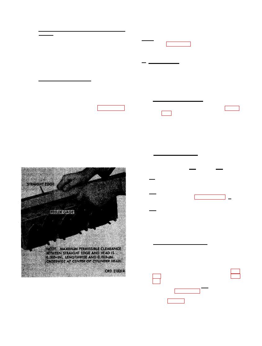
straightness as shown in figure 386.
permissible clearance described in fig-
The maximum permissible out of flat
ure 386, the cylinder head can be re-
when checking lengthwise is 0.005-inch.
faced using a surface grinder. When
The maximum out of flat when checking
cylinder head is refaced, grind valve
crosswise is 0.003-inch. Inspect studs
s e a t s as directed in paragraph (2)
(K- 6, K- 17, and K- 18) for bent condition
below. Replace the cylinder head when
or damaged threads. Inspect core hole
e x c e s s i v e grinding is r e q u i r e d to
plugs (K- 8 and K- 11) for secure fit and
straighten out gasket surface.
for evidence of coolant leakage.
(2) Valve seat grinding. When valve seats
can be repaired by regrinding or when
valve seats are to be replaced, grind
as described in (a) through (c) below.
(a) Use a 45 degree angle grinding stone to
grind valve seats.
(b) After grinding seat, check valve con-
tact as described in paragraph 198 b (2).
(c) Keep valve seat as near as possible
to center of valve face. Narrow seat
as necessary using a 20 degree grind-
ing stone. Valves should never seat at
the top or bottom of the face.
(3) Valve seat replacement. Replace valve
seats (K- 12 and K- 15) that cannot be
repaired by grinding. Remove seat using
any method which will not damage
counterbore of cylinder head machined
surface. Install new intake valve seat
(K- 15) using improvised replacer (fig.
seat as described in (a) above and as
shown in figure 387. Shrink the insert
by immersing in dry ice before instal-
FOR STRAIGHTNESS.
lation (fig. 388).
240
|
|
Privacy Statement - Press Release - Copyright Information. - Contact Us |