 |
|||
|
|
|||
|
Page Title:
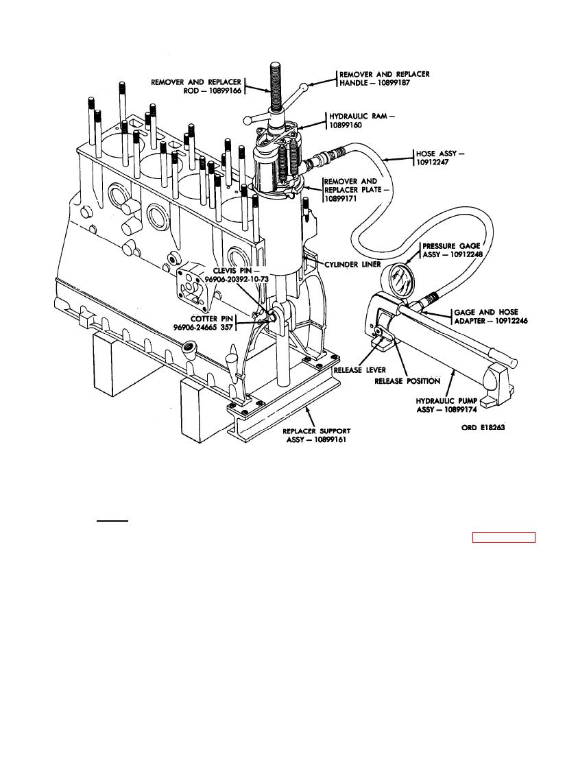
FIGURE 332. CYLINDER SLEEVE REMOVER AND REPLACER KIT - 8722925 AND RAM KIT - 10912249 SHOWING PROPER METHOD OF CYLINDER LINER... |
|
||
| ||||||||||
|
|
 RAM KIT - 10912249 SHOWING PROPER METHOD OF CYLINDER LINER INSTALLATION.
lease lever on pump, and repeat the
N o t e . The pistons in the hydraulic
pumping operation. Remove the liner
ram have a two-inch maximum travel.
from cylinder. Refer to figures 330
It will be necessary to remove the liner
and 331.
in two-inch increments.
(6) Place hydraulic pump release lever in
(7) Remove hydraulic ram kit, remover and
proper position for pumping (lever to
replacer kit, and liner.
left). Actuate the pump arm with slow
even strokes. When the sleeve has been
(8) Clean the cylinder bore with crocus
raised approximately two inches, turn
cloth dipped in dry-cleaning solvent or
hydraulic pump release lever to release
m i n e r a l spirits paint thinner. Clean
position (lever to right). This will allow
bore thoroughly and wash with dry-
the ram piston to drop into position for
cleaning solvent o r mineral spirits
another 2-inch lift. Turn handle down
paint thinner.
against hydraulic ram, reposition re-
204
|
|
Privacy Statement - Press Release - Copyright Information. - Contact Us |