 |
|||
|
|
|||
|
Page Title:
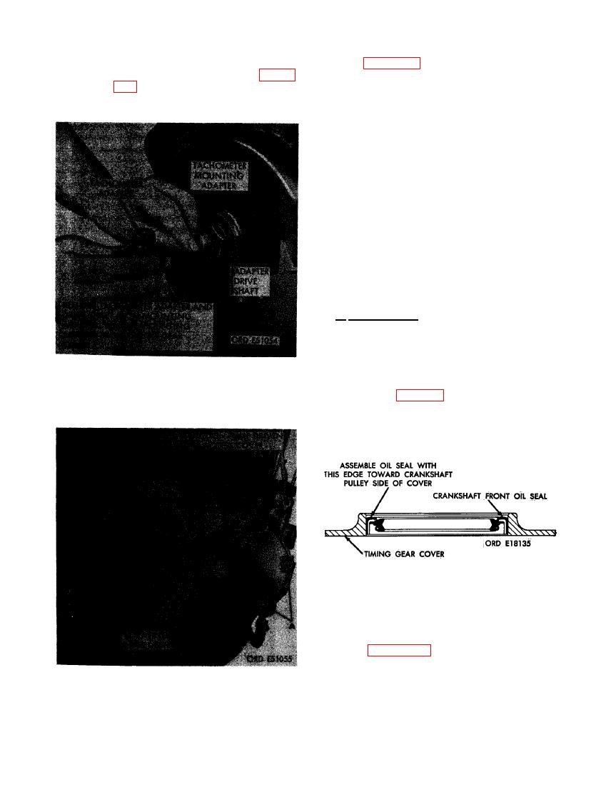
FIGURE 209. REMOVING OR INSTALLING TACHOMETER ADAPTER. |
|
||
| ||||||||||
|
|
 (8) Figure 210. (A) Remove three 3/8-inch
(7) Remove tachometer adapter, drive shaft,
plain nuts and 3/8- inch lock washers
and mounting adapter as shown in fig-
from the three studs. (B) Remove two
ure 209.
3/8-inch plain nuts, 3/8-inch heavy
lock washers, and 3/8 x 3-3/4 cap
screws. (C) Remove fuel injection pump
driven gear access cover. Remove and
discard cover gasket. (D) Remove 3/8-
inch plain nut, 3/8- inch lock washer,
and 3/8 x 1-1/4 cap screw. (E) Remove
1/2-inch plain nut, 1/2-inch lock
washer, and 1/2 x 2-3/4 cap screw.
(F) Remove seven 3/8 x 1-1/4 cap
screws and 3/8-inch lock washers se-
curing timing gear cover assembly (G)
Remove timing gear cover assembly.
Remove and discard timing gear cover
gasket.
(9) Remove crankshaft front oil seal from
timing gear cover assembly.
b. Installation. Install crankshaft front oil
seai as follows.
(1) The crankshaft front oil seal has a
double lip which must be installed in the
timing gear cover assembly with flange
edge away from cover mounting flange.
Refer to figure 211 for installation in-
TACHOMETER ADAPTER.
structions.
FOR CRANKSHAFT FRONT OIL SEAL.
(2) Figure 212. (A) Position crankshaft
front oil seal in bore of timing gear
cover assembly. (B) Install seal in
bore using arbor press and suitable
TIMING GEAR COVER ASSEMBLY.
press plate.
137
|
|
Privacy Statement - Press Release - Copyright Information. - Contact Us |
