 |
|||
|
|
|||
|
Page Title:
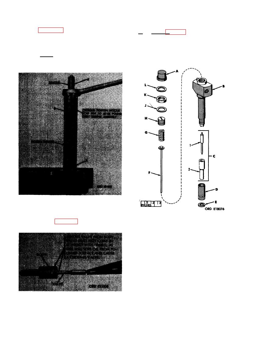
FIGURE 155. REMOVING OR INSTALLING VALVE |
|
||
| ||||||||||
|
|
 (3) Figure 154. (A) Position nozzle holder
f.
Cleaning (fig. 156).
in vise as shown. (B) Remove nozzle cap
nut. (C) Remove nozzle body and valve
(1) Soak the valve (C- 1) and nozzle body
as an assembly.
(C-2) in a carbon removing solvent to
remove major carbon deposits.
Note. The nozzle assembly must be
centered in the cap nut when installing
cap nut on nozzle holder.
NOZZLE CAP NUT AND NOZZLE
ASSEMBLY.
(4) Refer to figure 155 and remove the valve
A-Cap
F - Spindle
from the nozzle assembly.
B - Body
G - Spring
C - Nozzle assembly
H - Adjusting screw
1- Valve
J - Lock nut gasket
2- Nozzle body
K - Lock nut
D - Nozzle cap nut
L - Cap gasket
E - Gasket
ASSEMBLY - EXPLODED VIEW.
(2) Clean the valve (C- 1) with a soft cloth
or a felt pad and mutton tallow. The
valve can be held by the stem in a re-
volving chuck during this operation. A
piece of soft wood, well soaked in oil,
may be used for cleaning carbon from
VALVE.
the valve.
110
|
|
Privacy Statement - Press Release - Copyright Information. - Contact Us |