 |
|||
|
|
|||
|
Page Title:
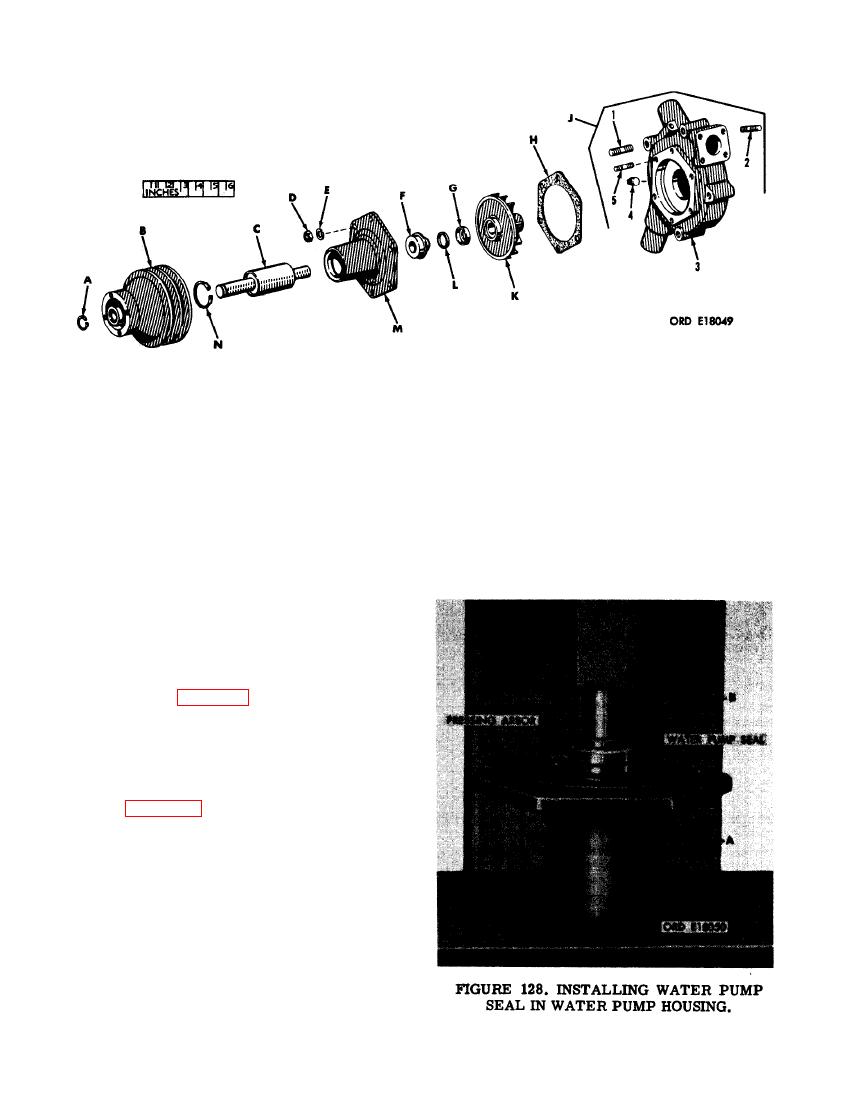
FIGURE 127. WATER PUMP ASSEMBLY - EXPLODED VIEW. |
|
||
| ||||||||||
|
|
 Pulley retaining ring
A-
J - Body assembly
B-
Pulley
1- 3/8 X 1-5/16 stud
Drive shaft
C-
2- 5/16 X 1- 1/4 stud
5/16-in. plain nut
D-
3-Body
E-
5/16-in. lock washer
4- 1/2-in. pipe plug
F-
Seal
5- 5/16 x 1- 1/4-stud
Seal seat housing
G-
K - Impeller
H-
Housing gasket
L - Seal seat
M - Water pump housing
N - Shaft retaining ring
(2) Refer to figure 125 and reverse the se-
quence of instructions to install the seal
seat and seal seat housing in impeller.
Note. The grooved surface on seal seat
must face the seal seat housing.
(3) Figure 128. (A) Mount water pump hous-
ing on a press plate as shown. (B) In-
stall water pump seal in water pump
housing using a suitable pressing arbor,
until flange of seal properly seats
against housing. The carbon face of seal
must be toward impeller side of housing.
98
|
|
Privacy Statement - Press Release - Copyright Information. - Contact Us |