 |
|||
|
|
|||
|
Page Title:
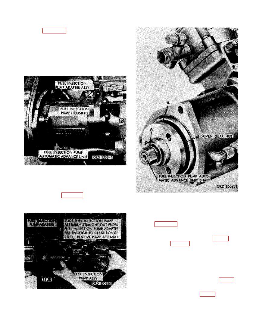
FIGURE 71. REMOVING OR INSTALLING FUEL INJECTION PUMP ASSEMBLY. |
|
||
| ||||||||||
|
|
 (17) Figure 70. (A) Remove 3/8-inch plain
nut and 3/8-inch lock washer from stud
extending through the fuel injection pump
automatic advance unit and flange of fuel
injection pump housing. (B) Remove two
3/8 x 1-1/8 cap screws and 3/8-inch
lock washers securing fuel injection
pump assembly to fuel injection pump
adapter assembly.
NECTING FUEL INJECTION PUMP
AT FUEL INJECTION PUMP
ADAPTER UNIT.
(18) Refer to figure 71 and remove the fuel
injection pump assembly.
FUEL INJECTION PUMP DRIVEN
GEAR HUB.
(19) Figure 72. (A) Remove 9/16-inch plain
nut and 9/16-inch lock washer from fuel
injection pump automatic advance unit
shaft using improvised tool (fig. 38) as
shown in figure 73. (B) Remove fuel in-
jection pump driven gear hub from shaft
using a suitable puller.
Note. When installing plain nut on shaft
the nut must be torque tightened. For
early model injection pumps equipped
with a Woodruff key in shaft (fig. 75)
torque tighten nut to torque of 50 pound
feet. Late model injection pumps do not
have a Woodruff key (fig. 74) and nut
must be torque tightened to 70 pound
feet.
FUEL INJECTION PUMP ASSEMBLY.
73
|
|
Privacy Statement - Press Release - Copyright Information. - Contact Us |