 |
|||
|
|
|||
|
Page Title:
REPAIR COOLANT AND TIME DELAY VALVE HOUSING INSERTS |
|
||
| ||||||||||
|
|
 TM 9-2520-270-34
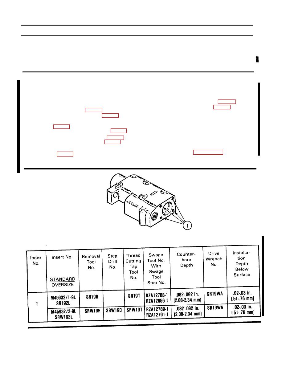
REPAIR COOLANT AND TIME DELAY VALVE HOUSING INSERTS
DESCRIPTION
This task gives the location and size of inserts used in the coolant and time delay valve housing. Part
or item numbers of tools, kits, and inserts, and working dimensions are given below. For procedures
to remove, repair, and install inserts, refer to Replace Inserts. See Page 2-171.
INITIAL SETUP
Materials/Parts:
Tools:
Sealant compound (Item 11, App B)
General mechanic's tool kit:
Transmission oil -- (Item 12, App B)
automotive -- (Item 33, App C)
Industrial goggles (Item 39, App C)
Personnel Required:
Inside/outside indicator caliper --
(Item 41, App C)
Track Veh Rep 63H10
Portable electric drill -- (Item 58, App C)
Screw threading set (Item 65, App C)
Equipment Conditions:
Socket wrench set -- (Item 88, App C)
Coolant and time delay valve housing
Transmission insert repair kit --
on workbench. See page 4-408.
(Item 103, App C)
Compressed air source, 30 psi
(207 kPa) maximum
REPAIR
STANDARD AND OVERSIZE INSERT REPLACEMENT INFORMATION
END OF TASK
4-415 (4-416 blank)
Change 1
|
|
Privacy Statement - Press Release - Copyright Information. - Contact Us |