 |
|||
|
|
|||
|
Page Title:
REPAIR COOLANT AND TIME DELAY VALVE ASSEMBLY |
|
||
| ||||||||||
|
|
 TM 9-2520-270-34
REPAIR COOLANT AND TIME DELAY VALVE ASSEMBLY
DESCRIPTION
This task covers: Disassemble (page 4-408). Assemble (page 4-411).
INITIAL SETUP
Materials/Parts:
Tools:
Transmission oil (Item 12, App B)
Crowfoot attachment---(Item 19A, App C)
Preformed packing
General mechanic's tool kit: automotive --
Preformed packing
(Item 33, App C)
Retaining ring
Inside/outside indicator caliper --
(Item 41, App C)
Personnel Required:
Machinist's vise (Item 47, App C)
Micrometer caliper set -- (Item 52, App C)
Track Veh Rep 63H10
Socket wrench adapter -- (Item 75, App C)
Socket wrench attachment (Item 80, App C)
Equipment
Conditions:
Socket wrench attachment (Item 83, App C)
Socket wrench set (Item 89, App C)
Coolant and time delay valve assembly on
Telescoping gage set -- (Item 93, App C)
workbench. See page 4-404.
Torque wrench -- (Item 99, App C)
Torque wrench -- (Item 100, App C)
Timing device-capable of measuring
15 seconds
DISASSEMBLE
NOTE
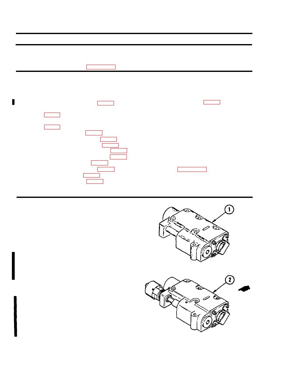
Two types of coolant and time delay valve
assemblies are in use. Portions of these
procedures apply to each valve assembly.
1. PLACE COOLANT AND TIME DELAY
VALVE ASSEMBLY IN VISE.
2. INSPECT VALVE ASSEMBLY AND
DETERMINE TYPE.
a. If valve assembly is type (1), go to
step 3.
b. If valve assembly is type (2), go to
step 3.1.
4-408
Change 3
|
|
Privacy Statement - Press Release - Copyright Information. - Contact Us |