 |
|||
|
|
|||
|
|
|||
| ||||||||||
|
|
 TM 9-2520-270-34
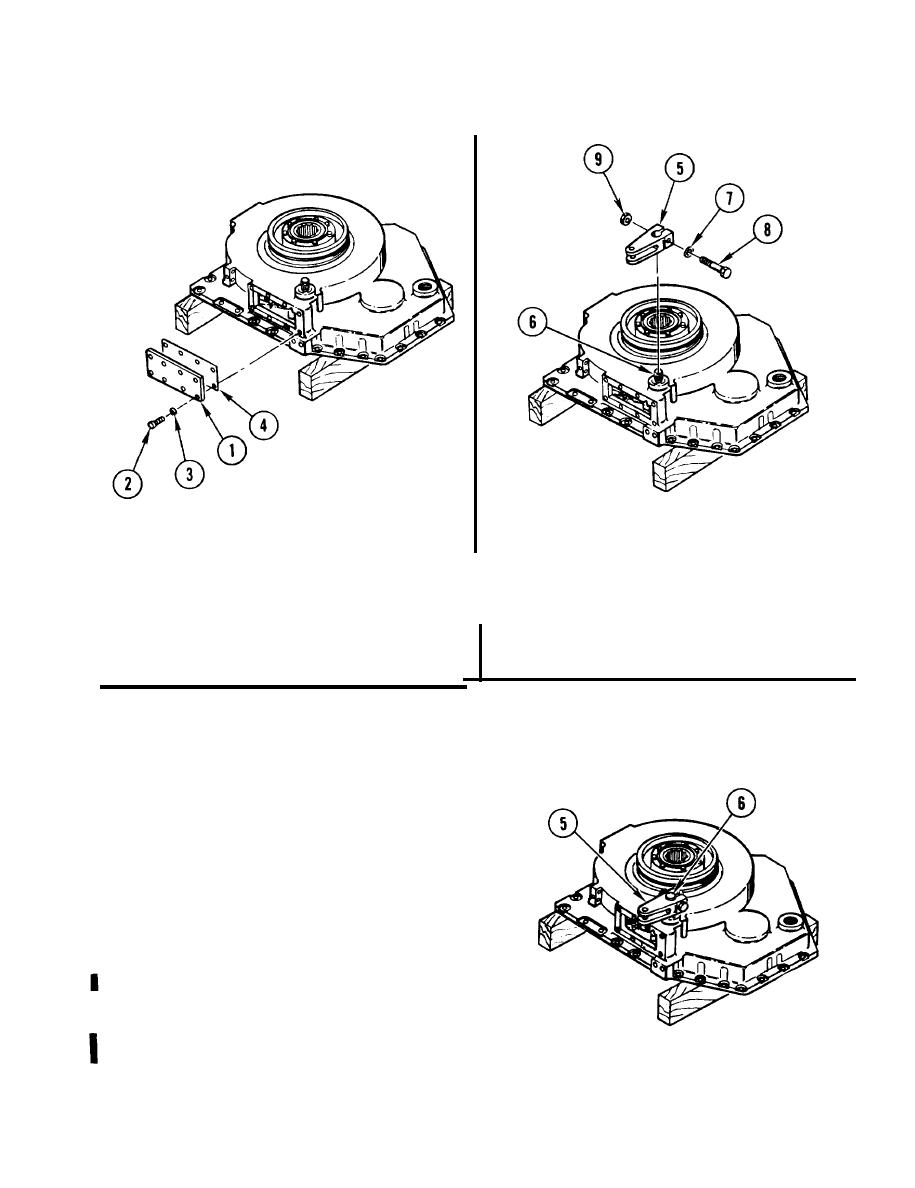
13. REMOVE ACCESS COVER (1), IF
INSTALLED.
Using 3/8-inch drive brace handle
a.
14. ATTACH LEVER ARM (5) TO
and 7/16-inch socket, remove eight
SHOULDERED SHAFT (6).
I
screws (2) and lock washers (3).
a. Position lever arm (5)
I
Discard lock washers.
b. Install washer (7), screw (8), and
b. Remove cover (1) and gasket (4).
self-locking nut (9).
Discard gasket.
15. ROTATE LEVER ARM (5) AND APPLY
FIRM PRESSURE TO ACTUATE
BRAKES.
a. If shaft (6) does not rotate, go to
step 20. If shaft does rotate, go to
step 17.
16. (DELETED)
GO TO NEXT PAGE
4-273
Change 1
|
|
Privacy Statement - Press Release - Copyright Information. - Contact Us |