 |
|||
|
|
|||
|
Page Title:
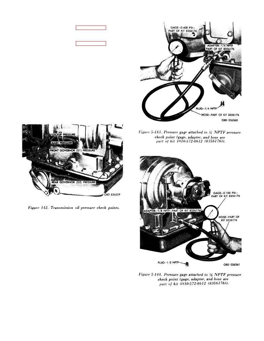
Figure 142. Transmission oil pressure check points |
|
||
| ||||||||||
|
|
 (2) The 0-400 psi gage, hose, and fittings
from oil gage kit 4910-572-8612, and the method
of attaching are shown in figure 5-143.
(3) The 0-100 psi gage, hose, and fittings
from oil gage kit 4910-5'72-8612, and the method
of attaching are shown in figure 5-144.
(4) The tapped holes in the transmission
housing, to which the oil cooler lines connect, are
shown in figure 5-145. Oil temperature, converter-
out pressure, and lubrication pressure may be
measured by installing suitable fittings, and
connecting gages to the lines which attach at these
openings.
(5) When connecting gages into lines attached
to the openings shown in figure 5-145, the con-
verter-out pressure and temperature gages both
must be connected into the oil line which attaches
at the rear opening. The lubrication pressure may
be taken at the line which attaches at the forward
opening.
|
|
Privacy Statement - Press Release - Copyright Information. - Contact Us |