 |
|||
|
|
|||
|
|
|||
| ||||||||||
|
|
 TM 9-2520-249-34& P
(6) In reverse gears during normal or pivot
NOTE
steer, the output at the side toward which the turn is
The transmission brakes must be
made rotates clockwise. The opposite side rotates
properly adjusted when using stall
counterclockwise. Both rotations are as viewed from the
check tool (29, table 3-1). Refer to
right side of the transmission.
paragraph 9-5a, below.
f. Converter Stall Test
CAUTION
(3) A low engine speed (under 2100 rpm)
While conducting a stall tests, do not let
may indicate that that the engine is not delivering full
oil temperature in the converter-to-cooler
power.
Refer to TM 9-2815-205-34 for engine
circuit exceed 325F.
The high-
instructions. If high (above 2400 rpm) or low (below
2100 rpm) engine speed is noted, refer to
temperature warning light comes on at
troubleshooting, chapter 4.
this temperature. With the transmission
in neutral, run the engine at 1000 to 1500
9-5.
Adjustments
rpm between tests to cool the oil to
a. Brakes
normal (1800 to 2200F).
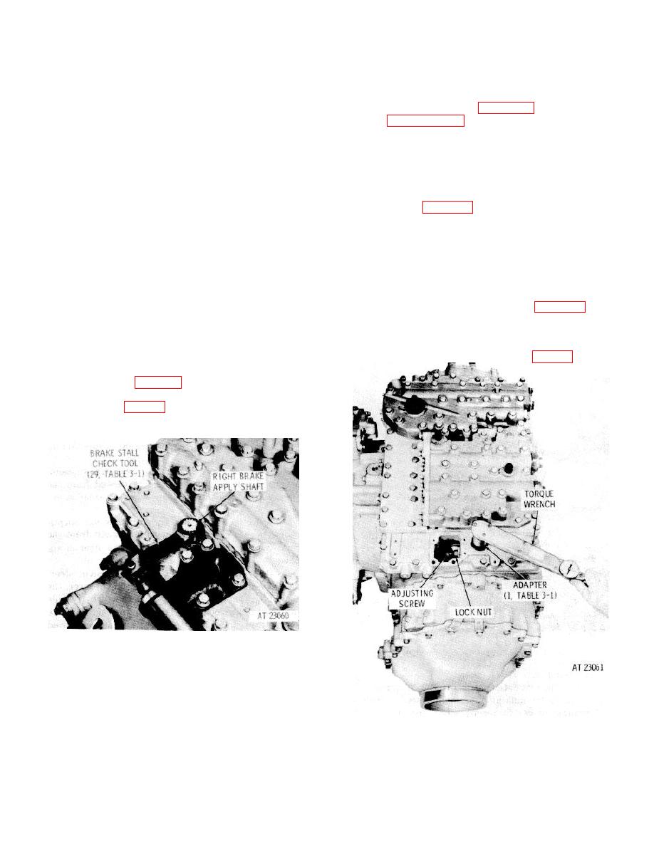
(2) Remove the linkage from the left and right
(1) A converter stall test is performed by
brake apply shafts, leaving the shaft splines exposed at
stalling the transmission output, putting the transmission
the top of the transmission. Remove the left and right
in fourth gear accelerating the engine to full throttle, and
brake inspection covers immediately forward of the
noting the maximum rpm the engine will attain. The
brake separately. Install adapter (1, table 3-1) on a
speed attained is then compared to normal stall speed
short 1/2-inch drive socket wrench extension. Use a
2100 to 2400 rpm). Number 2 diesel fuel should be
torque wrench and apply 100 pound feet rotating force
used in the 6V 53T engine during a stall test.
(clockwise on left side, counterclockwise on right side of
(2) To conduct converter stall tests in the
transmissions to the brake apply shaft (fig. 9-6).
vehicle, fully apply vehicle brakes.
To conduct
converter stall tests in the test stand, install the brake
stall check tool (29, table 3-1) after removing the brake
linkage and brake inspection cover at the right side of
the transmission (fig. 9-5). Tighten the stall check tool
until Apply on the brake indicator alines with the
stationary mark on the transmission top cover.
Figure 9-5. Brake stall check tool installed on
transmission.
Figure 9-6. Checking rotation of brake apply shaft
during adjustment of brake.
9-6
|
|
Privacy Statement - Press Release - Copyright Information. - Contact Us |
