 |
|||
|
|
|||
|
|
|||
| ||||||||||
|
|
 TM 9-2520-249-34& P
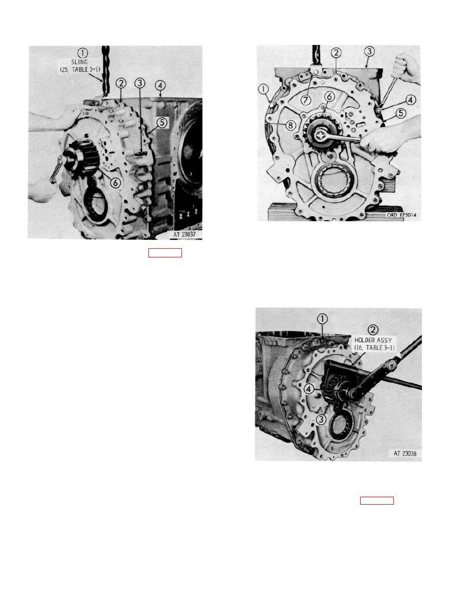
51 Install two 3/8-16 x 1 3/4-inch bolts (1 and 4),
and carefully draw output housing assembly (2)
against bevel gear housing (3) while rotating
50 Attach lifting sling (1) (25, table 3-1) at top of
output drive gear (16 back and forth. When the
output housing (2). Install two 3/8-16 x 4-inch,
output housing assembly is seated against the
headless guide bolts (3), 180 degrees apart, into
bevel gear housing, remove two bolts (1 and 4)
bevel gear housing (4). Install gasket (5) on
and two guide bolts (5 and 8). Remove lifting
bevel gear housing. Slide output housing (2)
sling (7).
onto guide bolts (3) and into position against
bevel gear housing (4).
NOTE
Adjust the hoist carefully and keep the output
housing assembly parallel with the bevel gear
housing. Rotate output drive gear (6) while
pressing the output housing assembly into
place. The reverse-range ring gear must spline
onto the cross shaft, the sun gear must mesh
with the carrier pinions. and the reverse-range
ring gear (brake hub internal teeth ) must mesh
with the pinions.
52 Install twenty-four 3/8-16 x 1 3/4-inch bolts (1).
24 plain washers and 24 lock-washers. Tighten
the bolts to 27 to 32 pound feet torque. Using
holder assembly) (2), (16, table 3-1 lock output
drive gear (3). Tighten bolt (4) to 200 to 225
pound feet torque.
8-21
|
|
Privacy Statement - Press Release - Copyright Information. - Contact Us |