 |
|||
|
|
|||
|
Page Title:
Section XXVI. LUBRICATION REGULATOR VALVE BODY ASSEMBLY-REPAIR |
|
||
| ||||||||||
|
|
 TM 9-2520-249-34&P
Table 7-21. Repair Standards (Main-pressure Regulator Valve, Lockup Regulator Valve, Oil Transfer Plate)
Wear limit
Reference
Size and fit
DS/GS
Foldout
Item
Point of measurement
of new parts
maintenance
10
41b
Inside diameter of valve bore in body....
1.1865 to 1.1875
10
46b
Outside diameter of valve ....................
1.1850 to 1.1855
10
41b.
Fit of valve in body ..............................
0.0010L to 0.0025L
**0.0045L
46b
10
41e
Inside diameter of valve bore in body ...
0.7015 to 0.7025
10
43a
Outside diameter of valve ....................
0.7000 to 0.7005
10
41e,
Fit of valve in body ..............................
0.00100L to 0.0025L
**0.0045L
43a
10
41 f
Inside diameter of valve bore in body ...
0.6870 to 0.6880
10
43b
Outside diameter of valve ....................
0.6855 to 0.6860
10
41f,
Fit of valve in body ..............................
0.0010L to 0.0025L
**0.0045L
43b
10
45a
Free length of spring ............................
3.90
*
10
45a
Length under load ...............................
1.98 at 7.42 to
1.98 at 7.27 lb
8.02 lb
*Replace when worn beyond new dimensions.
**Wear is allowed on either or both mating parts so long as fit is within the specified limit.
Section XXVI. LUBRICATION REGULATOR VALVE BODY
ASSEMBLY-REPAIR
7-152. Description
Refer to paragraph 2-24 for description of the lubrication
regulator valve body assembly.
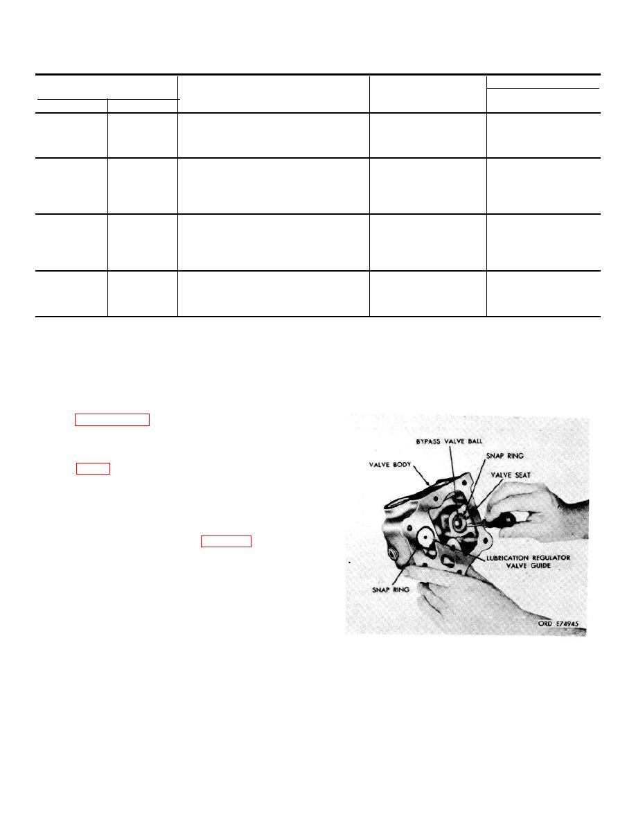
7-153. Disassembly
a. Remove retaining ring (74), guide (76),
spring (78) and valve (80) from lubrication regulator
valve body (84).
b. Remove retaining ring (82) and regulator
valve seat (83) from valve body (84).
check valve seat and the cooler bypass valve ball.
Figure 7-54. Removing for installed cooler
bypass valve snapring.
7-48
|
|
Privacy Statement - Press Release - Copyright Information. - Contact Us |
