 |
|||
|
|
|||
|
Page Title:
Figure 7-41. Installing output clutch piston return spring. |
|
||
| ||||||||||
|
|
 TM 9-2520-249-34& P
c. Place a flat, smooth plate (approximately 7
x 7 inches) on the clutch plates as shown in figure 7-40.
d. Apply a press force of 600 to 2,000 pounds
on the clutch group as shown in figure 7-40, and
measure and record dimension B.
of the snapring which retains the output clutch piston
housing. Record this as dimension C.
f.
Substitute the three dimensions recorded
for the letters in the formula A (B + C)=clutch clearance.
If the clearance is between 0.070 and 0.090 inch, the
clutch may be assembled from the parts at hand. If the
clearance is greater than 0.090 inch, select a thicker
than 0.070 inch, select a thinner piston.
NOTE
The exact thickness of the piston is etched
on the piston.
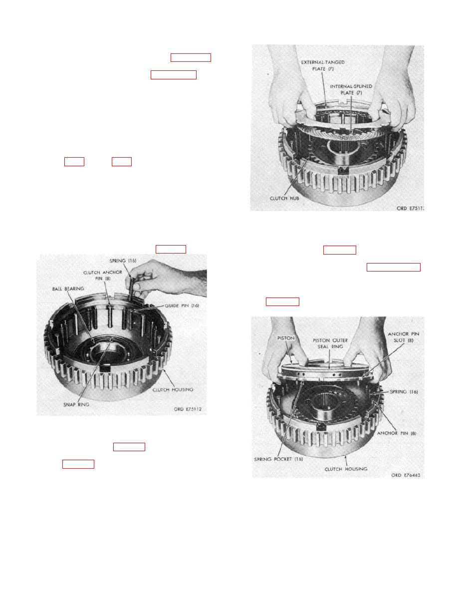
Figure 7-42. Installing output clutch plates.
g. With
the
proper
clutch
clearance
established, assemble the clutch as outlined below.
k. Install, alternately, seven internal-splined
h. Install the ball bearing into the clutch
and seven external-tanged clutch plates. beginning with
housing and retain it with the snapring (fig. 7-41).
an internal-splined plate (fig. 7-42).
l.
Install the expander and piston outer
sealring onto the piston as outlined in paragraph 7-55.
m. Install the piston, larger diameter first, into
the clutch housing. Make certain that all of the springs
seat in the counterbored spring pockets in the clutch
piston (fig. 7-43). Shaking the piston will help seat the
springs.
Figure 7-41. Installing output clutch piston return spring.
i.
Install eight clutch anchor pins, 16 spring
guide pins and 16 springs (fig. 7-41).
j.
Install the clutch hub, shorter side of hub
downward (fig. 7-42).
Figure 7-43. Installing output clutch piston.
7-35
|
|
Privacy Statement - Press Release - Copyright Information. - Contact Us |
