 |
|||
|
|
|||
|
Page Title:
Reverse- 1 Gear, Pivot Left Steer |
|
||
| ||||||||||
|
|
 TM 9-2520-249-34&P
2-44.
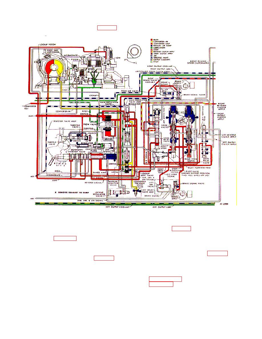
Figure 2-12. Hydraulic system, reverse-1 gear, pivot left steer operation-schematic view.
a. Operational Circuits.
Thus driving
left steer clutch (fig. 2-13) and allows the left reverse
clutch to exhaust.
condition uses the same circuitry as forward, first gear,
d. Reverse-1 Signal Circuit. Signal pressure
normal left steer (para 2-41) except that the right
reverse clutch is used as the driving component and left
in this circuit causes a reduction in main pressure. The
steer clutch is used as the steering member. The flow
pressure is reduced in this driving condition to limit the
through the steer valve circuits is also the same as
torque through the driving clutches (para 2-39c).
described for first gear, normal left steer (para 2-41).
b. Pivot Valve (pivot water steer position).
NOTE
The position of the pivot valve does not affect the
The mechanical functions required for
circuits involved for this driving condition.
this travel operation are described in
c. Steer Relay Valve. Signal pressure in the
paragraph 2-52e, and illustrated in
reverse signal circuit enters near the bottom of the steer
relay valve and forces it upward. In this position, the
steer relay valve directs regulated steer pressure to the
2-27
|
|
Privacy Statement - Press Release - Copyright Information. - Contact Us |