 |
|||
|
|
|||
|
Page Title:
Reverse-2 Gear, Straight Travel Operation |
|
||
| ||||||||||
|
|
 TM 9-2520-249-34&P
Thus, the engaged clutches cause the vehicle to travel
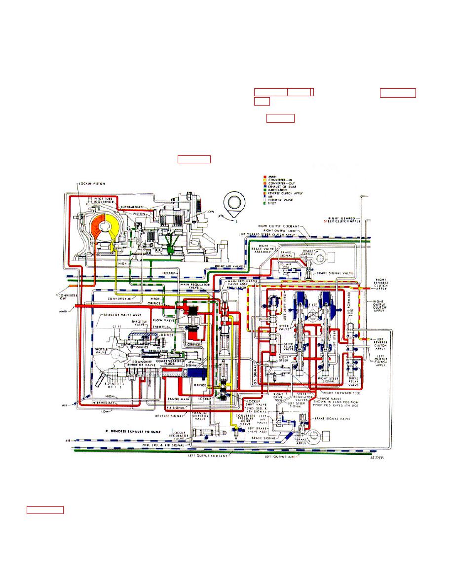
d. Reverse Signal Circuit. Main pressure is
in reverse.
directed from the manual selector valve to the steer
NOTE
relay valve. The oil enters near the bottom of the steer
relay valve but above the geared steer signal plug. This
The related mechanical functions required
causes the steer relay valve to move to the upward
for this travel condition are described in
position.
e. Drive Relay Valve. Main-pressure oil from
the steer valves is directed to the drive relay valve. The
2-40. Reverse-2 Gear, Straight Travel Operation
drive relay valve, in the upward position, directs the oil
through the left, and right, drive feed passages to the
steer relay valve.
f.
Steer Relay Valve. The steer relay valve
directs main-pressure oil through the reverse clutch
apply lines to the respective reverse clutches (fig. 2-13).
Figure 2-8. Hydraulic system, reverse 2 gear, straight travel operation-schematic view
a. Operational Circuits. This driving condition
reverse-2 detent. This allows a main-pressure port
(upper passage) to index with an intermediate range
uses the same circuitry as reverse-1, straight travel.
clutch apply port. The low-range clutch (or high-range
clutch) is exhausted simultaneously
engaged.
b. Manual Selector Valve.
The valve is
moved toward the left until the retaining ball rests in
2-22
|
|
Privacy Statement - Press Release - Copyright Information. - Contact Us |