 |
|||
|
|
|||
|
|
|||
| ||||||||||
|
|
 TM 9-2520-246-34
e. Input Shaft.
(1) Place the input shaft ball bearing on the input
shaft. Place the input shaft between two parallel
blocks. spline downward. Using an arbor press, press
the input shaft ball bearing onto the shaft. Secure
bearing to input shaft using a new snapring. See fig.
NOTE
Coat the input shaft and ball bearing bore
with white lead pigment, Fed Spec TT-W-
261C, before pressing the ball bearing
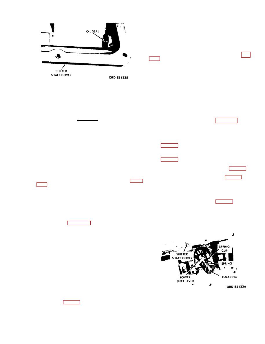
Figure 3-45. Removal of First and Reverse
assembly on the shaft.
Shifter Shaft Oil Seal
(2) Coat the input shaft roller bearing bore with
c. Mainshaft.
a light coating of grease. artillery and automotive
(GAA), MIL-G-10924. Install the input shaft roller
bearings. Insert the last roller bearing end wise into the
CAUTION
bearing assembly. (See para 3-9 note.)
Do not press directly on the flange of the
sleeve. Use a short piece of pipe or tubing
3-11. Assembly.
and press on end of sleeve. Direct pressure
on the flange of the sleeve may damage it.
a. Install countershaft front bearing and washer.
(See fig. 3-32.)
(1) Slide the second speed gear on the mainshaft.
b. Install new countershaft front bearing retainer
Coat the second- and third-speed synchronizer sleeve
(See fig. 3-32.)
bore and mainshaft with a light coating of grease,
artillery and automotive (GAA), MIL-L-10924. Start
the sleeve on the mainshaft. Place into the press, face
down. between two parallel bars. Press sleeve into
position and secure it using a new snapring. See figure
snapring.
synchronizer.
e. Install countershaft rear bearing retaining nut.
Tighten nut to 120-150 lb-ft torque. Secure nut to
(2) Coat the fourth-speed gear sleeve and
mainshaft using a new cotter pin (fig, 3-30).
mainshaft with white lead. Fed Spec TT-W-261C.
Make an opening in the adapter puller large enough
NOTE
to slip through. Position the third-speed gear and
fourth-speed gear sleeve to main drive shaft and press
After applying torque. tighten nut to
into place. See figure 3-35 for the correct positioning
closest cotter pin hole.
of third-speed gear and fourth-speed gear sleeve.
(3) Install mainshaft fourth-speed gear and thrust
washer. Secure in place using a new snapring.
NOTE
Be sure snapring is fully seated in the
mainshaft groove.
d. Mainshaft Rear Bearing Cap.
(1) Press seal into place using a block of wood
and a press.
Figure 3-46. Removal of Lower Shift Lever.
Lever Spring, and Spring Cap
(2) See fig. 3-22 for positioning of seal.
3-19
|
|
Privacy Statement - Press Release - Copyright Information. - Contact Us |