 |
|||
|
|
|||
|
|
|||
| ||||||||||
|
|
 TM 9-2520-246-34
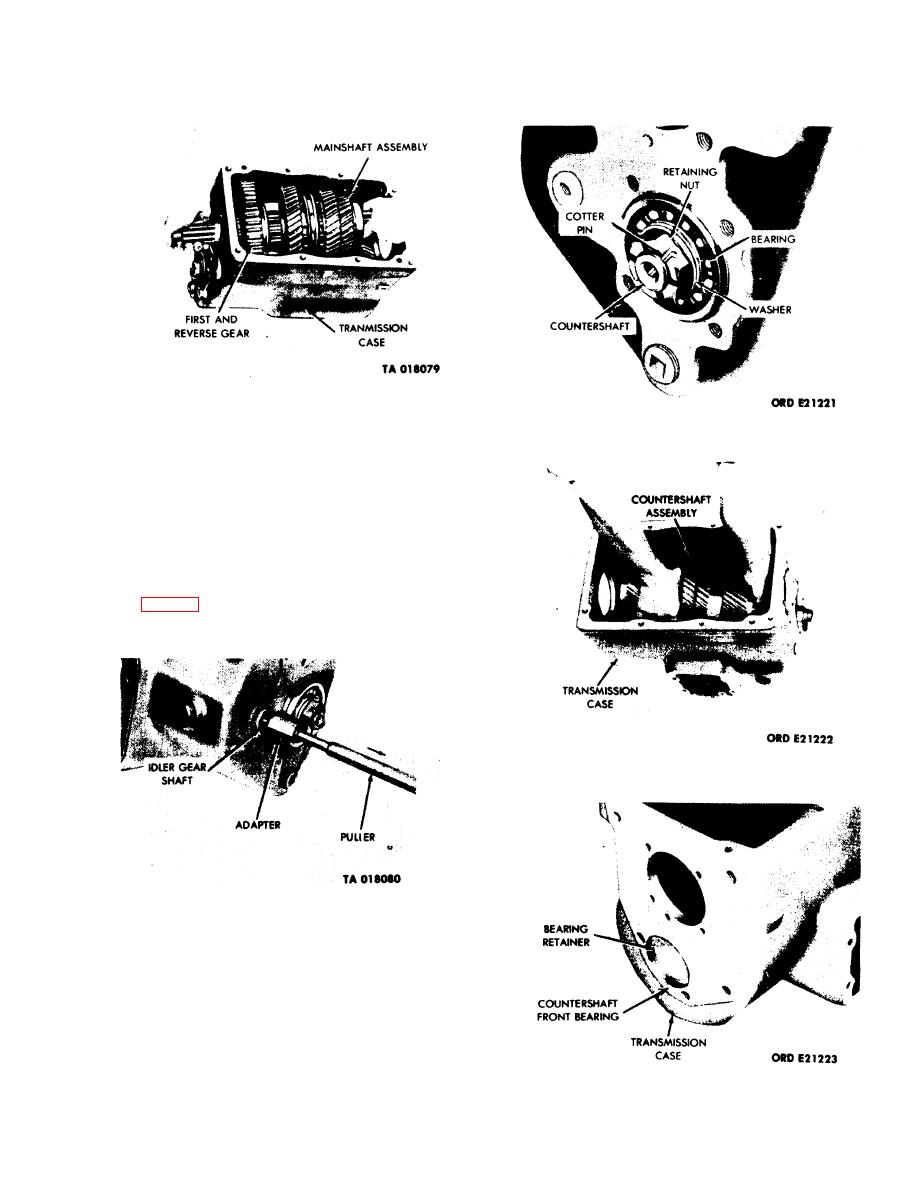
Figure 3-28. Removal of Mainshaft Assembly.
Figure 3-30. Removal of Countershaft Rear Bearing.
3-9. Disassembly of Subassemblies.
CAUTION
Use extreme care not to lose roller bearings
from the mainshaft end of the input shaft.
a. Input Shaft Assembly. Using a pair of pliers,
remove the input shaft ball bearing retainer snapring.
(See fig. 3-33.) Place the input shaft between two
parallel blocks, spline upward. Using an arbor press,
push the input shaft ball bearing from the shaft.
Figure 3-31. Removal of Countershaft Assembly.
Figure 3-29. Removal of Idler Gearshaft and
Idler Gear Assembly.
NOTE
When installing the input shaft roller
bearings, keystone construction of assembly
requires endwise insertion of last roller.
Also, coat the input shaft and ball bearing
bore with white lead pigment, Fed Spec
TT-W-261C, before pressing the ball
bearing assembly back on the shaft.
Figure 3-32. Removal of Countershaft Front Bearing.
3-15
|
|
Privacy Statement - Press Release - Copyright Information. - Contact Us |