 |
|||
|
|
|||
|
Page Title:
CHAPTER 3. REPAIR OF TRANSMISSIONS |
|
||
| ||||||||||
|
|
 TM 9-2520-246-34
CHAPTER 3
REPAIR OF TRANSMISSIONS
Section I. DESCRIPTION, OPERATION, AND DATA (MODEL 3052)
because the input gear and countershaft drive gear are
3-1. General. This chapter contains the repair
continuously meshed. Because the countershaft gears
instructions for transmission models 3052 and 3053A.
are integral with, or keyed to, the countershaft, power
This section provides the description, operation, and
is continuously available at any countershaft gear.
data pertinent to the five-speed synchromesh,
Due to the constant mesh of second, third, and fifth
manually shifted transmission model 3052.
(overdrive) gears of the mainshaft and countershaft,
locking any one of these gears to the mainshaft causes
3-2. Description.
the mainshaft to rotate at a rate proportionate to the
ratio of that gear to the countershaft gear with which
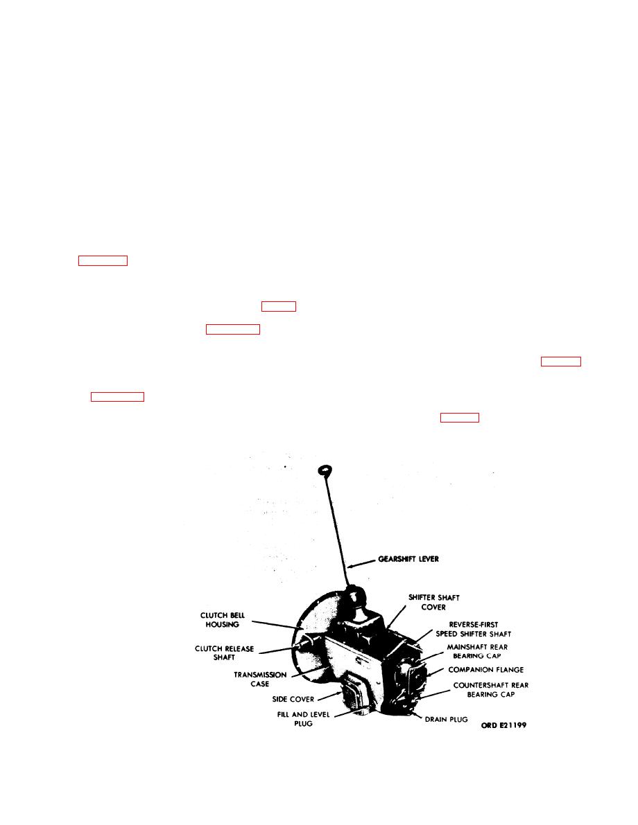
a. General. Transmission model 3052, shown in
it is meshed. Rotation of the mainshaft is in the same
direction as that of the input shaft, except in reverse
vehicles using a gas engine, not equipped with a front
gear.
winch. This same transmission is used with vehicles
equipped with a front winch. The transmission has a
(2) Reverse Gear Power Flow. Power is
power takeoff mounted on the left side (fig. 3-2) which
transmitted by the countershaft second-speed reverse-
is used to drive the winch. The construction of the
idler gear and the constantly meshed reverse-idler gear
transmission is illustrated in figures 3-3 to 3-11.
to the mainshaft first-speed reverse gear, which is
splined to the mainshaft, driving the mainshaft in the
b. Operation.
direction opposite to the input shaft. (See fig. 3-12,
view A.)
(1) Power Flow. The flow of power through the
transmission gear train and shafts is graphically shown
(3) First Speed Power Flow. Power is transmitted
in figure 3-12. In operation, the input gear is
by the countershaft and mainshaft first-speed gears to
constantly applying power to the countershaft,
the mainshaft. (See fig. 3-12, view B.)
regardless of the speed selected by the operator,
Figure 3-1. Transmission Models 3052 and 3053A - Exterior Components.
3-1
|
|
Privacy Statement - Press Release - Copyright Information. - Contact Us |
