 |
|||
|
|
|||
|
Page Title:
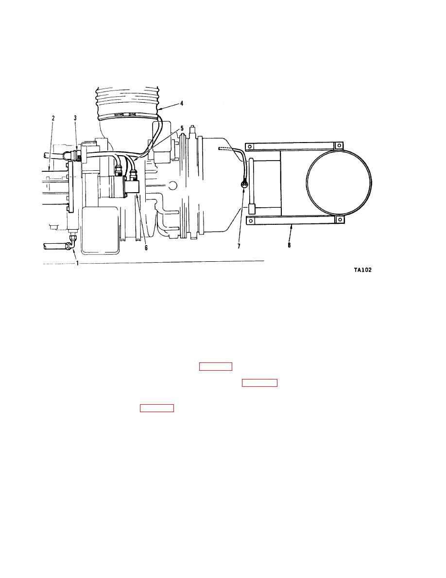
Figure 3-1. Mounting and Connecting the APU |
|
||
| ||||||||||
|
|
 TM 55-4920-424-13&P
1.
Fuel Inlet Line
2.
APU Support Housing
3.
APU Co ntrol Harness
4.
Air Inlet Silencer
5.
Tachometer Generator Harness
6.
Tachometer Generator
7.
Thermocouple
8.
Exhaust Duct Assembly
Figure 3-1. Mounting and Connecting the APU
(1) Using a suitable hoist assembly, or equivalent, position APU and engage spline drive adapter. Move APU
forward until it contacts face of speed increaser mounting pad.
(2) Secure APU to speed increases with nuts and washers removed in step a. (3), preceding.
(3) Secure APU to bracket assembly (122, figure 5-1) with wing bolt assembly (121).
(4) Install flexible duct section from air inlet silencer (4, figure 3-1) to air inlet shroud on APU. Secure flexible
duct with clamp provided.
c. Connecting the APU. (See figure 3-1.)
(1) Remove protective cap from fuel inlet filter fitting on APU, and connect flexible fuel supply line (1) from
check stand. Install protective cap on check stand dummy fitting.
(2) Connect check stand control harness (3) to harness receptacle on APU.
Tighten harness connector
securely.
(3) Install tachometer generator (6)(furnished with stand) on aft pad of APU speed switch, using coupling, nuts,
and washers furnished with stand.
3-2
|
|
Privacy Statement - Press Release - Copyright Information. - Contact Us |