 |
|||
|
|
|||
|
Page Title:
Chapter 3. OPERATING INSTRUCTIONS |
|
||
| ||||||||||
|
|
 TM 55-4920-411-13&P
Section I. CONTROLS AND INSTRUMENTS
All operator's controls, indicators, and connectors
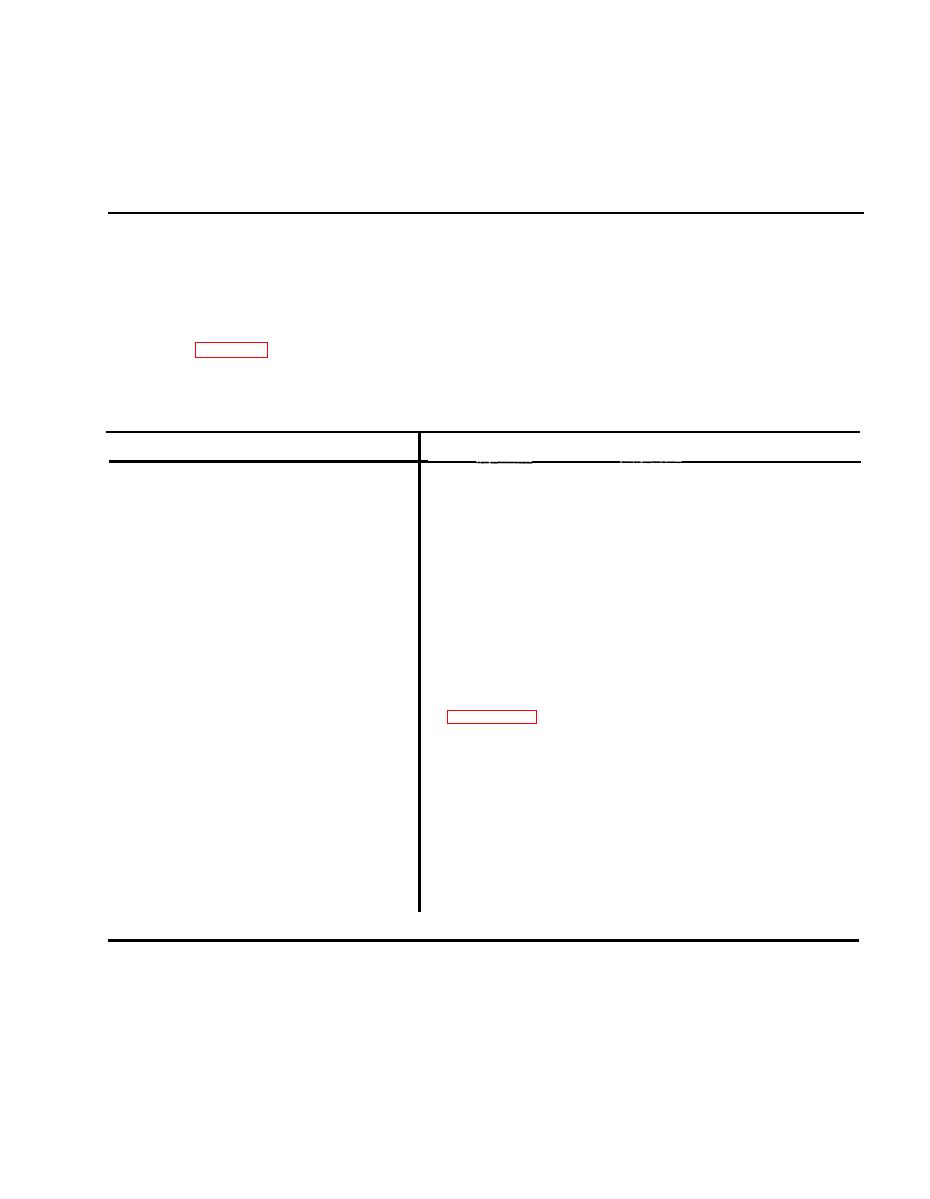
are shown in Figure 3-1 and described in Table 3-1.
Table 31. Indicator and Control Functions
Indicator, Control or Connector
Function
Connects frequency and temperature outputs through test
SIGNAL OUTPUT APU (J2) connector
cable to start sequence control. Also connects switch inputs
to test set.
Power input connector connects to power cable.
115 VAC, 50 400 HZ POWER (J1)
Manually-actuated sequence timer displays intervals over
SECONDS display
range 0-99 seconds.
Starts, stops, and resets SECONDS timer.
START/STOP RESET switch
Monitor APU switch closures. Lamps L1 through L6 monitor
Lamps L1 L6
exciter and start fuel valve, main fuel valve, max fuel valve,
bypass valve, high oil temp, and low oil pressure,
respectively.
Adjusts frequency output, selected by FUNCTION SWITCH,
VAR FREQ ADJ (F1)
in 1% rpm units over range 5% rpm. See Note in
Selects 0, 5, 15, 70, 90 or 110% rpm frequency output when
FUNCTION SWITCH (S2)
VAR FREQ ADJ is in zero position
Tests lamps L1 L6.
LAMP TEST switch (S4)
Simulates low oil pressure, high oil temperature, and normal
LOP/HI OIL TEMP/NORM switch (S3)
operating conditions.
Adjusts simulated chromel-alumel signal output.
TEMP OUTPUT, 400 -- 800C (R1)
Controls application of power to signal unit.
POWER switch (S1)
Indicates when power is applied to (on) or removed from (off
Power indicating lamp (DS1)
test set.
|
|
Privacy Statement - Press Release - Copyright Information. - Contact Us |