 |
|||
|
|
|||
|
Page Title:
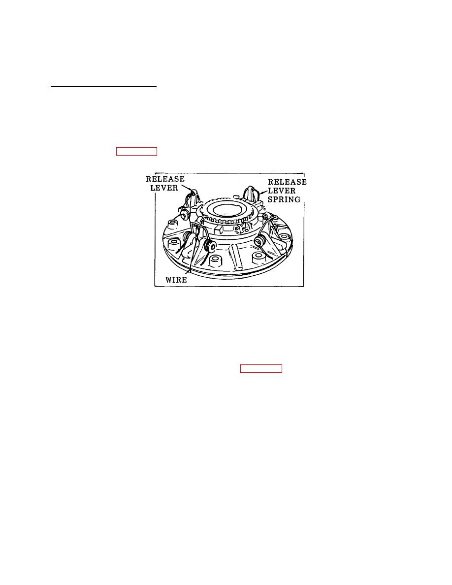
Figure 4-60. Clutch Release Levers. |
|
||
| ||||||||||
|
|
 TM 55-1930-208-24
4-17. CLUTCH REPAIR-Continued.
a. Clutch Disassembly-Continued.
(d) Reverse the clutch drive shaft on the bed of the press and remove the second bearing in the same
manner.
(18) With the clutch assembly removed from the clutch drive shaft, proceed with the dis ssembly of the clutch
a
as follows:
(a) Refer to figure 4-60 and hold the clutch release levers away from the clutch adjusting ring with wire.
Figure 4-60. Clutch Release Levers.
(b) Raise the end of the clutch adjusting ring lockup out of the groove in the hub of the outer clutch
pressure plate. Then, remove the clutch adjusting ring by turning it counterclockwise off the hub of
the outer clutch pressure plate.
(c) Remove the wire from the clutch release levers.
(d) Separate the outer clutch pressure plate (30, figure 3-58), and center clutch pressure plate (31) from
the assembly.
(e) Remove screws (32) and separate the adjusting ring lock plate (33) from the adjusting ring.
(f) Remove screw (34), adjusting ring lock (35), and adjusting ring lock spring (36) front clutch adjusting
ring (37).
(g) Remove retaining rings (38), plain washers (39), pins (40), and plain washers (41). Remove clutch
release levers (42) and springs (43) from the inner clutch pressure plate (44).
4-80
|
|
Privacy Statement - Press Release - Copyright Information. - Contact Us |