 |
|||
|
|
|||
|
Page Title:
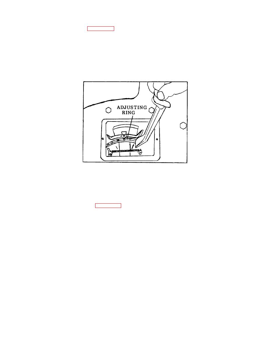
Figure 3-101. Clutch Adjustment. |
|
||
| ||||||||||
|
|
 TM 55-1930-208-24
b. Clutch Adjustment. (Refer to figure 3-101).
(1) Rotate the clutch, if necessary, to bring the clutch adjusting ring lock within reach.
(2) Raise the end of the adjusting ring lock up out of the splined groove in the hub of the outer clutch pressure
plate. Then, while holding the clutch drive shaft to prevent the clutch from turning, turn the clutch adjusting ring
clockwise and tighten the clutch until the desired pressure on the outer end of the hand lever is obtained. When the
clutch is properly adjusted, heavy pressure is required at the outer end of the hand lever to move the throwout linkage to
the "over center" or locked position.
Figure 3-101. Clutch Adjustment.
(3) After the clutch is properly adjusted, reinstall the end of the clutch adjusting ring lock in one of the splined
grooves in the hub of the outer clutch pressure plate.
(4) Install inspection hole cover (figure 3-100).
3-169
|
|
Privacy Statement - Press Release - Copyright Information. - Contact Us |