 |
|||
|
|
|||
|
Page Title:
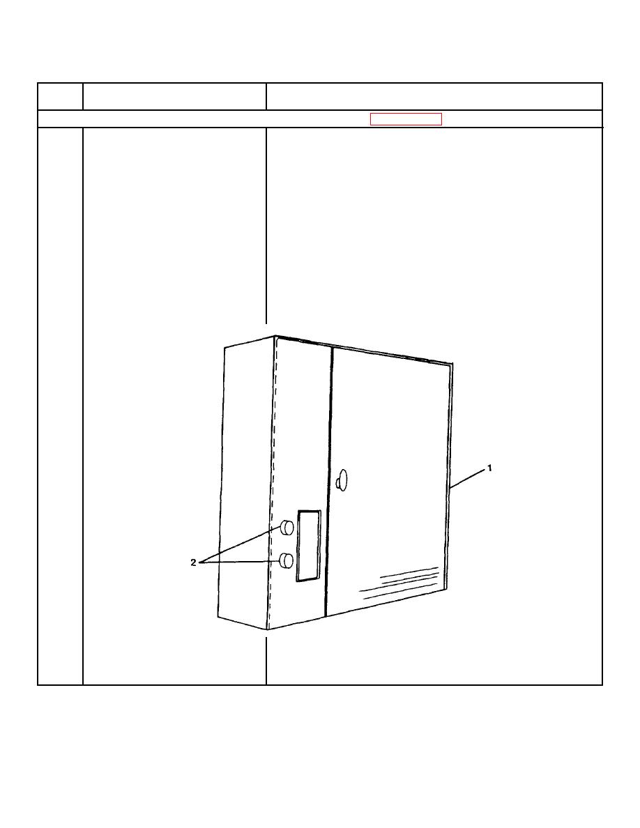
FIGURE 2-65. Exhaust Ventilator Control Cabinet. |
|
||
| ||||||||||
|
|
 TM 55-1915-200-10
Table 2-1. Description of Operator's Controls and Indicators - CONT
Key
Control or Indicator
Function
Exhaust Ventilator Control Cabinet (FIGURE 2-65)
1
Cabinet Door
Allows access to electrical system
controls and the detergent pump system.
2
STOP/START Pushbuttons
START button places ventilator in
operation. STOP button stops the
ventilator and automatically starts the
cleaning cycle.
FIGURE 2-65. Exhaust Ventilator Control Cabinet.
2-176
|
|
Privacy Statement - Press Release - Copyright Information. - Contact Us |