 |
|||
|
|
|||
|
Page Title:
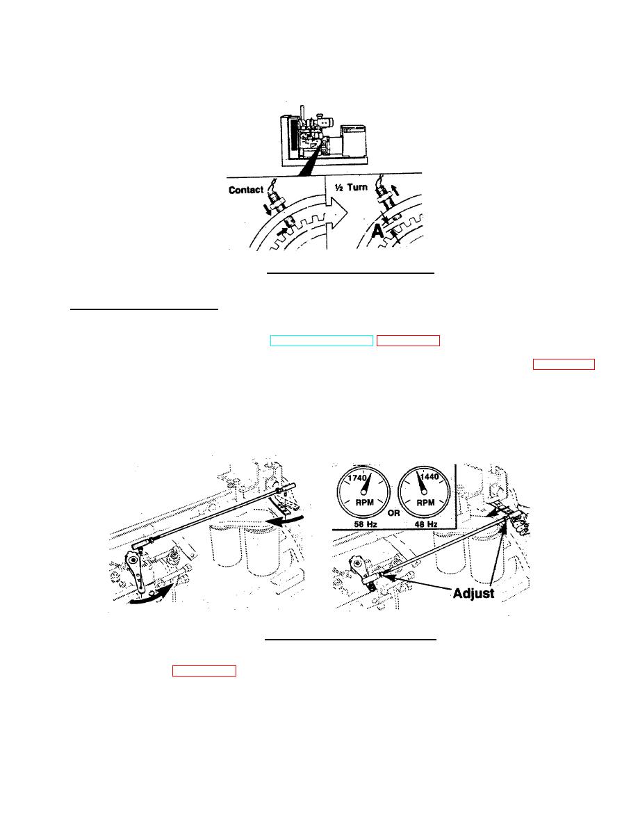
FIGURE 3-7. Magnetic Speed Sensor Adjustment. |
|
||
| ||||||||||
|
|
 TM 55-1905-223-24-4
(2)
Back off sensor +F turn. Secure lock nut. A=7.71 to 1.067mm (0.28 to .042 inch).
FIGURE 3-7. Magnetic Speed Sensor Adjustment.
b. Adjust Governor Actuator Lever.
(1)
Position fuel pump throttle lever in the full throttle position and the actuator i the idle position. Install the
n
linkage and start the generator set. (TM 55-1905-223-10) (FIGURE 3-8)
(2)
While holding the actuator arm in the idle position, adjust the linkage to obtain the following: (FIGURE 3-8)
60 Hz Operation -
approximately 58 Hz, 1740 RPM
50 Hz Operation -
approximately 48 Hz, 1440 RPM
FIGURE 3-8. Install Linkage/Adjust Actuator Lever.
(3)
Adjust the high idle adjusting screw to allow for the excessive travel needed to maintain the maximum
power required.(FIGURE 3-9)
A=.635mm (0.25 inch)
3-21
|
|
Privacy Statement - Press Release - Copyright Information. - Contact Us |
