 |
|||
|
|
|||
|
Page Title:
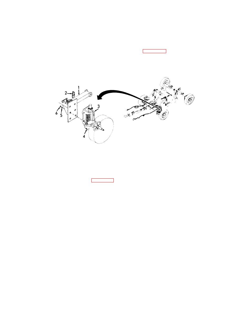
Figure 3-22. Shock Absorbing Spring Assembly, Removal. |
|
||
| ||||||||||
|
|
 TM 55-1740-203-13&P
3-20. LEFT AND RIGHT SHOCK ABSORBING SPRING
A S S E M B L I E S - Continued.
Removal.
a.
(1) Remove shock absorbing spring assembly (3, Figure 3-22) from front axle frame(l).
(a) Remove six nuts (6), six lockwashers (5), six bolts (4), and
bracket (2).
(b) Separate spring assembly (3) from front axle frame (1).
Figure 3-22.
Shock Absorbing Spring Assembly, Removal.
b.
Disassembly.
(1)
Remove cap (1, Figure 3-23) from knuckle (2).
(a) Remove three bolts (3) and three lockwashers (4).
(b) Lift cap (1) from knuckle (2).
Remove kingpin (5).
(2)
(a) Remove capscrew (6).
(b) Lift kingpin (5) from knuckle (2).
(3)
Note and record position of dust covers (7), washer (8), and
spring support assembly (9).
(4)
Remove bracket (10) from knuckle (2) and disassemble.
(a) Remove bracket (10) from knuckle (2).
( b ) Remove three dust covers (7), washer (8), spring support
assembly (9), six springs (11), and three spring guides
(12).
(c) Separate springs (11) from spring guides (12).
( d ) Remove two grease fittings (13).
GO TO NEXT PAGE
3-55
|
|
Privacy Statement - Press Release - Copyright Information. - Contact Us |
