 |
|||
|
|
|||
|
Page Title:
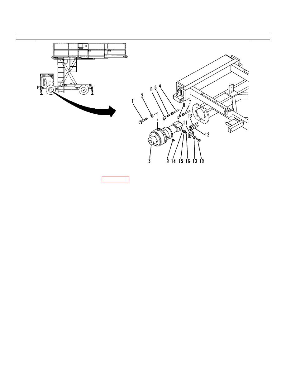
Figure 3-29. Hydraulic Motor, Brake, and Drive Hub, Replacement. |
|
||
| ||||||||||
|
|
 TM 55-1730-228-13&P
3-28. HYDRAULIC ROTOR, BRAKE AND DRIVE HUB ASSEMBLY- REPLACE (Continued)
3-28
Figure 3-29. Hydraulic Motor, Brake, and Drive Hub, Replacement.
(4) Remove eight capscrews (1, Figure 3-29) and washers (2) securing the hub assembly (3) to the flange.
(5) Place a drip pan under the frame member. Disconnect brake hose (4) and fitting (5) from elbow (6). Plug
the line to prevent foreign matter from entering.
(6) Slide hub assembly out 3" (76 mm). Remove case drain hose (7) from elbow (8).
(7) Remove elbow (6) from brake housing. Plug housing to prevent foreign matter from entering.
(8) Turn the assembly 900 counterclockwise and remove bleeder valve (9).
(9) Use an overhead hoist and suitable straps to support the drive hub. Install a strap between wheel hub and
mounting flange.
(10) Slide the assembly from frame housing about 15 inches. Reinstall bleeder valve (9) in brake housing.
(11) Tag the hydraulic hoses at the adapter block (11) for ease of identification during reassembly. Remove
two banjo fittings (10) securing drive motor adapter block (11). Remove block (11), hydraulic hoses (12)
and spacers (13). Remove preformed packing (14), washer (15) and preformed packing (16). Plug the
block, motor and hoses to prevent foreign matter from entering.
GO ON TO NEXT PAGE
3-68
|
|
Privacy Statement - Press Release - Copyright Information. - Contact Us |