 |
|||
|
|
|||
|
|
|||
| ||||||||||
|
|
 TM55-1730-228-13&P
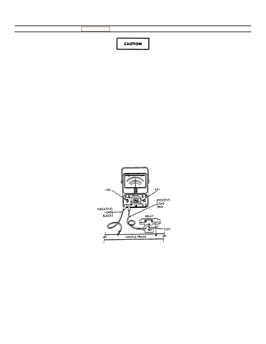
3-12. RESISTANCE CHECKS (Figure 3-14)
3-12
Never attempt to make resistance checks until all sources of power connected to the circuit or device to be
checked are disconnected. The multimeter will be damaged if this procedure is not followed.
a. All electrical circuits have some resistance. Some resistances, however, are so small and others so large they
cannot be read on the same scale. When a reading is obtained, it indicates the circuit has continuity (no breaks
or openings). The following procedure must be followed to perform resistance or continuity checks:
(1) Place the SCALE SELECTOR switch in the +DC position.
(2) Rotate the range selector switch to the required range:
(a) R x 1 to measure resistance between 0 and 2,000 ohms and to test for continuity.
(b) R x 100 to measure resistance between 0 to 200,000 ohms.
(c) R x 10,000 to measure resistance between 0 and 20 megohms.
b. Plug the black lead into the Jack marked COMMON and the red lead into the Jack marked +. Touch the ends of
the leads together and turn the ZERO OHMS knob until the pointer is at zero.
c. Separate the ends of the meter leads, and clip the leads across the portion of the circuit or component being
checked. (Either of the leads may be clipped to the measurement points.)
Figure 3-14. Resistance Check With Multimeter.
GO ON TO NEXT PAGE
3-13
|
|
Privacy Statement - Press Release - Copyright Information. - Contact Us |