 |
|||
|
|
|||
|
|
|||
| ||||||||||
|
|
 TM 55-1730-228-13&P
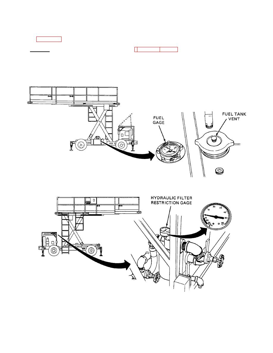
(4) FUEL TANK VENT-Use this valve when operating the SPEMS. Turn counterclockwise to open, clockwise to
close. See Figure 2-5.
c. Indicators. Operator indicators are listed below. See Figures 2-5 and 2-6.
(1) FUEL GAGE-Shows how much fuel is left in the fuel tank. Fill tank when needle is at or below 1/4.
(2) HYDRAULIC OIL FILTER RESTRICTION PRESSURE GAGE-Indicates when filter needs to be changed.
Change filter when needle points in red area. Both hydraulic suction and return filters each have a gage.
Figure 2-5. Fuel Tank.
Figure 2-6. Hydraulic Filter.
2-4
|
|
Privacy Statement - Press Release - Copyright Information. - Contact Us |