 |
|||
|
|
|||
|
Page Title:
REMOVING AND INSTALLING KINGPINS |
|
||
| ||||||||||
|
|
 TM 55-1730-224-13 & P
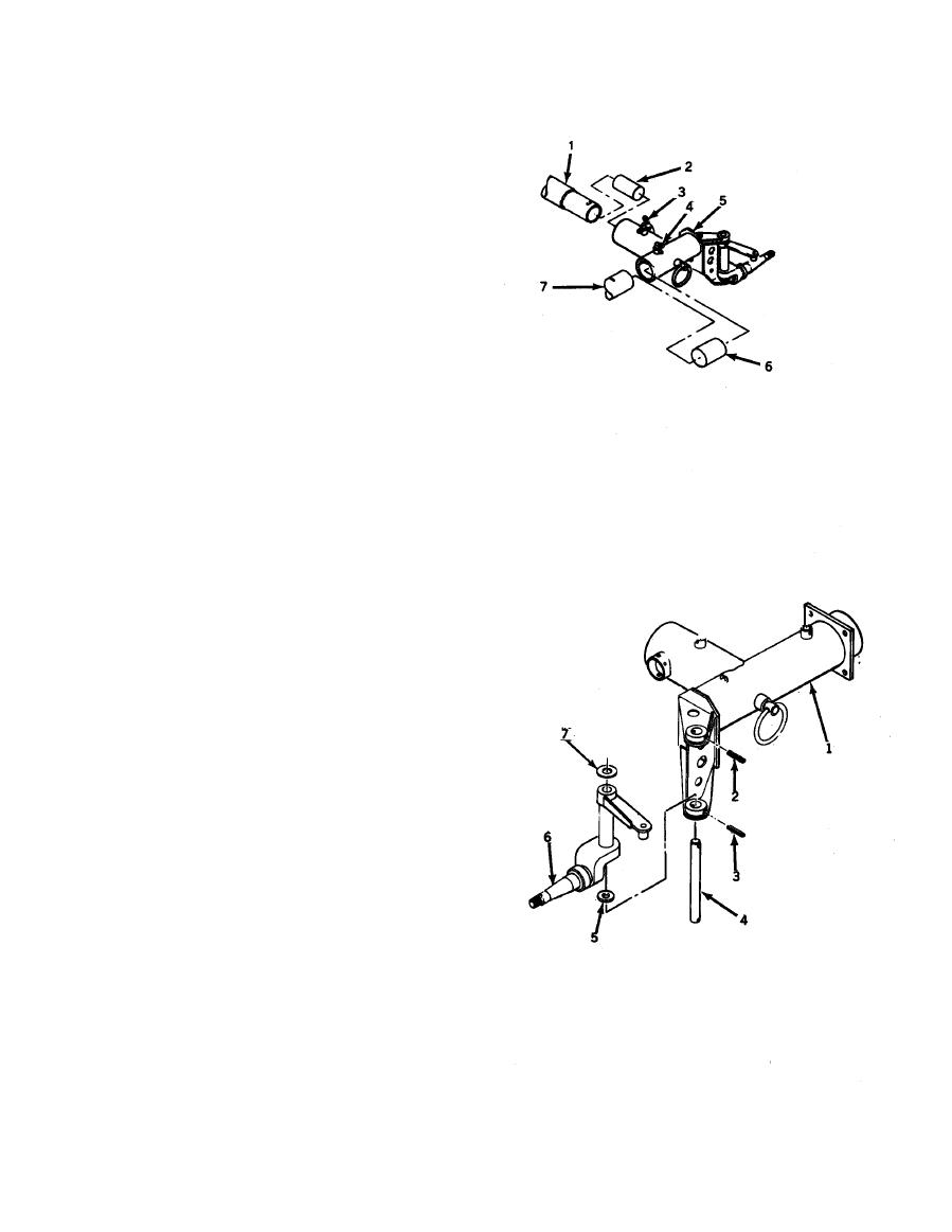
b. Left.
1. Support frame tubes (1) and
(7).
2. Fold back rubber boots (2)
and (6) onto corner assembly
tubes.
3. Remove lockpins (3) and
(4).
4. Pull corner assembly (5)
back from frame tubes (1) and (7).
PINS (AVIM).
1. Drive spring pins (2) and
(3) out of corner assembly (1) .
2. Drive kingpin (4) out of
holes.
3. Pull out spindle (6) and
thrust washers (5) and (7).
4. Replace worn parts as
needed.
5. Reinstall spindle (6) and
thrust washers (5) and (7). Align
holes.
6. Push kingpin (4) in place.
Align spring pin holes.
7. Drive spring pins in place.
3-23
|
|
Privacy Statement - Press Release - Copyright Information. - Contact Us |