 |
|||
|
|
|||
|
Page Title:
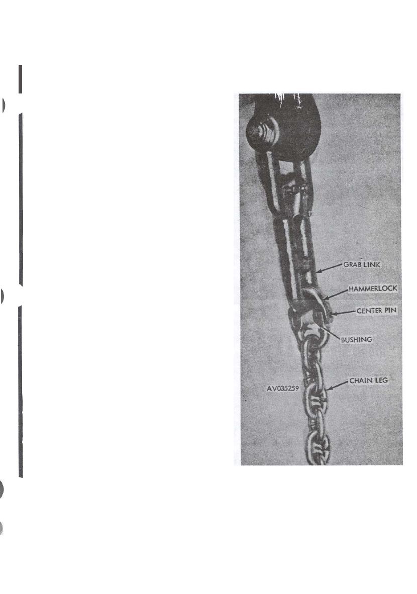
Figure A. Hammerlock Installed Between Chain Leg and Crab Link Assembly. |
|
||
| ||||||||||
|
|
 I
TM 55-1670-259-20
(d) Place a 6 l/4-inch-long web keeper around the
sling webbing at a point 2 inches below the connector
link lower attaching loop at the bottom of the sling.
(e) Install the locking forks in the bottom sliding
web keeper using procedures in (b) and (c) above.
(2) Position an end link of the chain leg on one end
of the hammerlock.
(3) Slip the other half of the hammerlock through the
narrow end of the grab link.
(4) Join the two parts of the hammerlock together
(fig. 2-1A).
(5) Place the center bushing in the middle of the
hammerlock.
(6) Insert the center pin in one side of the hammer
lock and gently tap with a mallet while insuring that
the pin passes through the center bushing and the op
posite side of the hammerlock.
( 7 ) I n s e r t s p a c e r into the nylon web loop lo-
cated below the bottom sliding web keeper (fig. 2-2).
(8) Position the bottom loop and spacer between the
top fork of the grab link. Insure that the spacer is a-
lined with the bolt holes in the top of the grab link.
(9) Insert the 4-inch-long bolt through one side of
the grab link, through the spacer, and through the op
posite side of the grab link.
(10) Attach the 3/4-inch
lock nut
to the threaded
end of the bolt and tighten, using two
open-end adjust-
able wrenches or other suitable tools,
until a minimum
of one and a half threads are showing
between the end
of the bolt and the lock nut (fig. 2-3).
(11) Attach the remaining two bottom loose ends of
the nylon sling leg to a connector link (fig. 2-3).
(12) Fasten the end of the connector link with two
metal screws, using a flat-tip screwdriver.
(13) Assemble each of the remaining three sling
l e g s for the sling assembly using procedures (1)
through (12) above.
(14) Position the tops of the four nylon slings adja-
cent to each other.
CAUTION
Upon completion of web ring assembly, insure
that the web ring connector link is positioned
Figure
A. Hammerlock Installed Between Chain Leg
to the extreme right side of the web ring to avoid
and Crab Link Assembly.
inadvertent contact with a helicopter cargo hook.
Change 1
2-5
|
|
Privacy Statement - Press Release - Copyright Information. - Contact Us |