 |
|||
|
|
|||
|
Page Title:
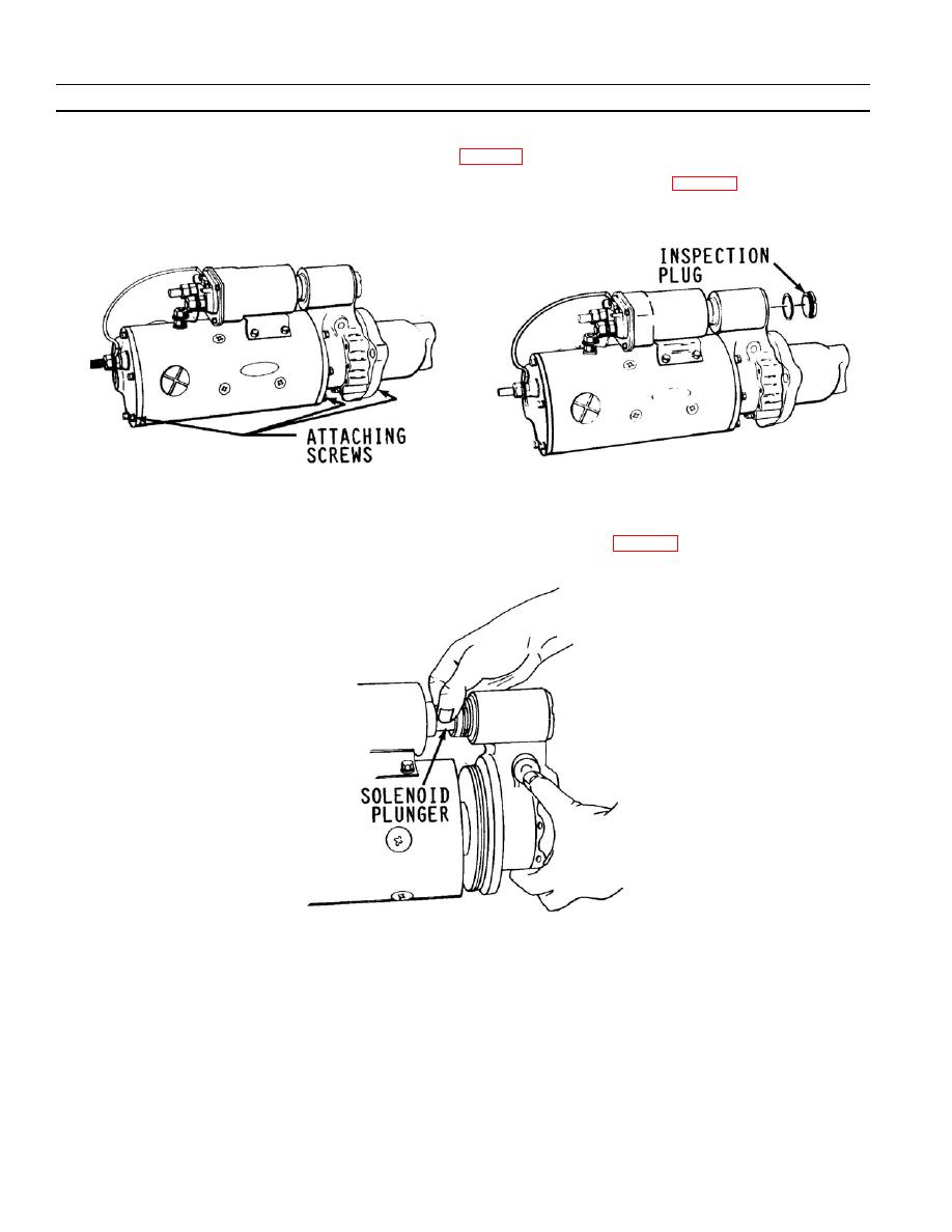
Figure 2--6. Location of Housing Attaching Screws |
|
||
| ||||||||||
|
|
 TM 9- 2920- 232- 34&P / TO 38X14- 2- 32
-
-
-
- -
TROUBLESHOOTING INSTRUCTIONS - CONTINUED
-
0005 00
7) Housing Attaching Screws. If starter produces excessive noise because a housing is not securely
fastened, check and/or torque attaching screws (fig. 2--6) to 144--192 lb--in (16.3 to 21.7 Nm).
8) Shift Lever. Remove the inspection plug for access to shift lever adjusting nut (fig. 2--7) if looseness is
indicated.
9) Separate lever housing with drive end housing with assembled parts (fig. 2--8) to check for suspected
binding in shift lever or drive clutch assembly by manually moving solenoid plunger.
0005 00- 4
-
|
|
Privacy Statement - Press Release - Copyright Information. - Contact Us |
