 |
|||
|
|
|||
|
Page Title:
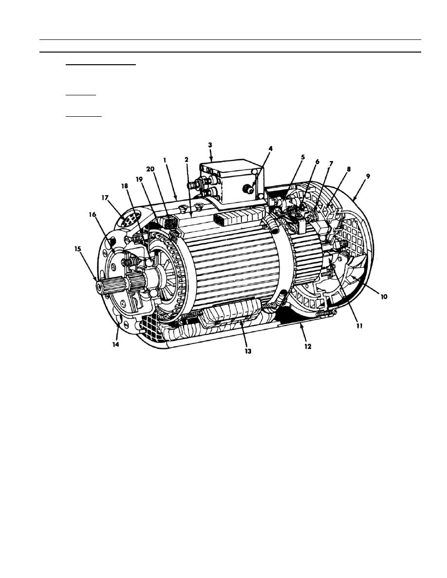
Figure 1--2. Sectional View of Typical Generator Assembly. |
|
||
| ||||||||||
|
|
 TM 9- 2920- 224- 34&P
-
-
-
EQUIPMENT DESCRIPTION AND DATA - CONTINUED
-
0002 00
c.
Drive Shaft Assembly. The drive shaft assembly (15) consists of a flexible splined shaft and a friction damper
mechanism (16). Flexibility is obtained with damper mechanism to absorb sharp peaks which may occur in
d. Armature. Armature (19) rotates in a pair of ball bearings (11 and 18). Both bearings are sealed and
permanently lubricated.
e. Cooling Air. The flow of cooling air is provided by a fan (10) driven by the armature, by an electrically driven
axial fan (on 10889713) or by a remote source of air ducted to the end bell (8) (on 11642898).
1.
Stator assembly
11.
Commutator end bearing
2.
Pole shoe
12.
Brush cover band assy
3.
Filter assembly
13.
Interpole coil
4.
Ground lead
14.
Keyhole--type mounting hole
5.
Brush spring
15.
Drive shaft assembly
6.
Brush assembly
16.
Damper mechanism
7.
Brush holder
17.
Air--outlet grille
8.
End bell
18.
Drive end bearing
9.
Fan cover
19.
Armature
10.
Cooling fan
20.
Field coil
0002 00- 3
-
|
|
Privacy Statement - Press Release - Copyright Information. - Contact Us |
