 |
|||
|
|
|||
|
Page Title:
Installation of Tappet Assembly. |
|
||
| ||||||||||
|
|
 TM 9-2910-226-34
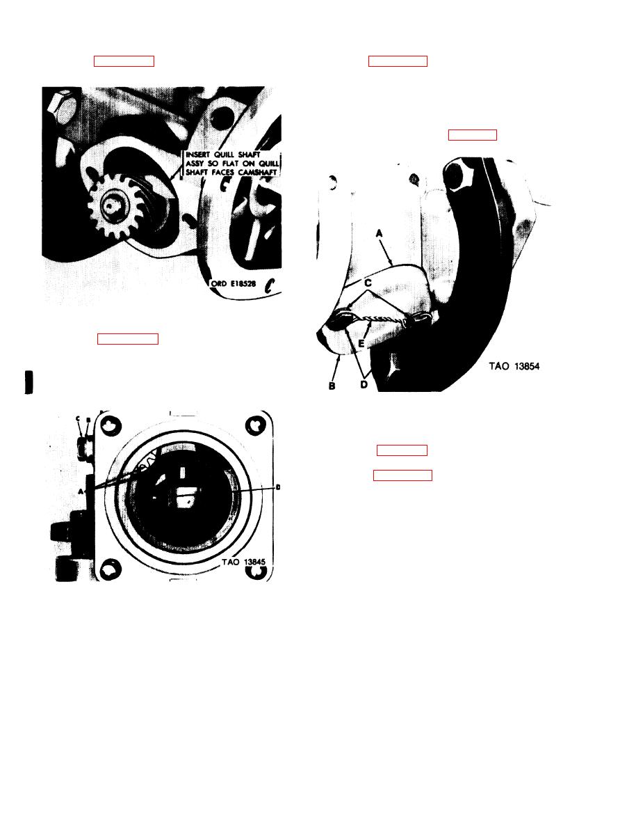
pad gasket with a thin coat of sealer, MIL-S-45180 or
equivalent. Install quill shaft pad gasket (A) and quill
shaft pad cover (B). Secure cover with two copper
gaskets (C) and machine screws (D). Torque tighten ma-
chine screws to 50-60 inch-pounds. Screws will be lock
wired at governor installation (para 3-43).
Figure 3-115. Installing quill shaft assembly.
so open tooth alines with housing mark (A), Install cop-
per gasket (B) and machine screw (C). Torque tighten
machine screw to 80-90 inch-pounds and secure with
locking wire.
Figure 3-117. Installing quill shaft pad cover.
3-39. Installation of Tappet Assembly.
a. Assembly. The tappet assembly was assembled
during repair (para 3-29).
NOTE
Refer to figure 3-118 for selection of tappet,
spring, and spring seat.
Figure 3-116. Installing quill shaft assembly in housing.
3-72
Change 2
|
|
Privacy Statement - Press Release - Copyright Information. - Contact Us |
