 |
|||
|
|
|||
|
Page Title:
Figure 3-58. Removing dust cover and operating lever two-piece |
|
||
| ||||||||||
|
|
 TM 9-2910-226-34
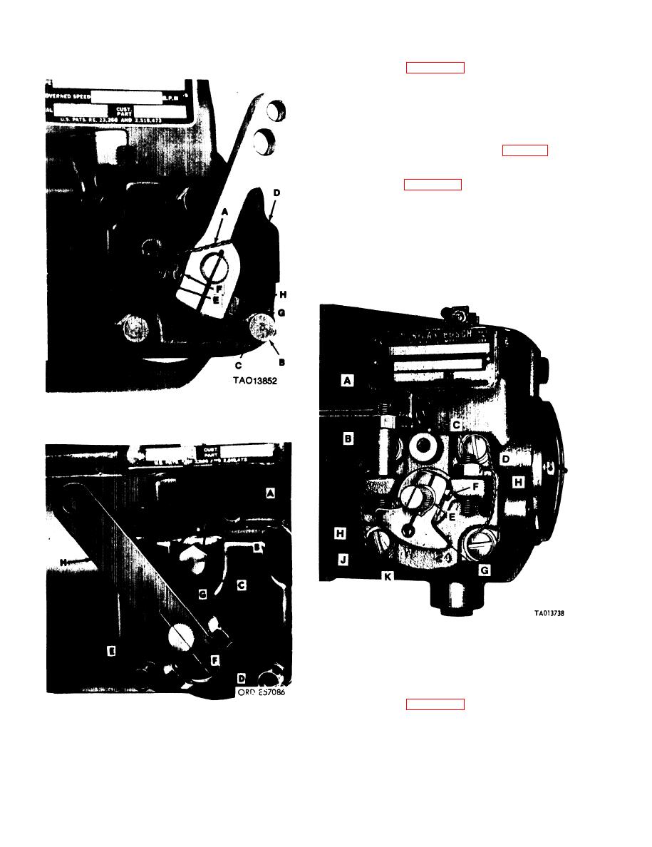
(6) Refer to figure 3-60. Loosen locknuts (B and
D). Remove idle adjustment screw (A) and locknut
(B), high speed adjustment screw (C), and locknut
(D).
NOTE
Sub-paragraph (7) below does not apply to
code A or early code G pumps.
(7) Remove retaining ring (E, fig. 3-60) using
suitable pliers. Remove clamping screw (F) and stop
lever (G).
(8) Refer to figure 3-60. Cut locking wire (H) and
remove four bearing mounting machine screws (J).
Remove and discard four gaskets (K).
NOTE
Code F injection pumps were equipped with
two bearing mounting studs. At
disassembly these should be discarded and
replaced with machine screws.
Figure 3-58. Removing dust cover and operating lever
two-piece.
Figure 3-60. Removing adjustment screws, stop lever,
operating shaft and associated parts.
NOTE
Paragraphs (9), (10) and (11) do not apply to
code A injection pumps.
(9) Refer to figure 3-61. Remove operating shaft
and bearing (A) and associated parts. Remove and
discard operating shaft bearing gasket (B).
Figure 3-59. Removing dust cover and operating lever
one-piece.
3-40
|
|
Privacy Statement - Press Release - Copyright Information. - Contact Us |
