 |
|||
|
|
|||
|
Page Title:
Section III. REPAIR OF FUEL INJECTION PUMP COMPONENTS |
|
||
| ||||||||||
|
|
 TM 9-2910-226-34
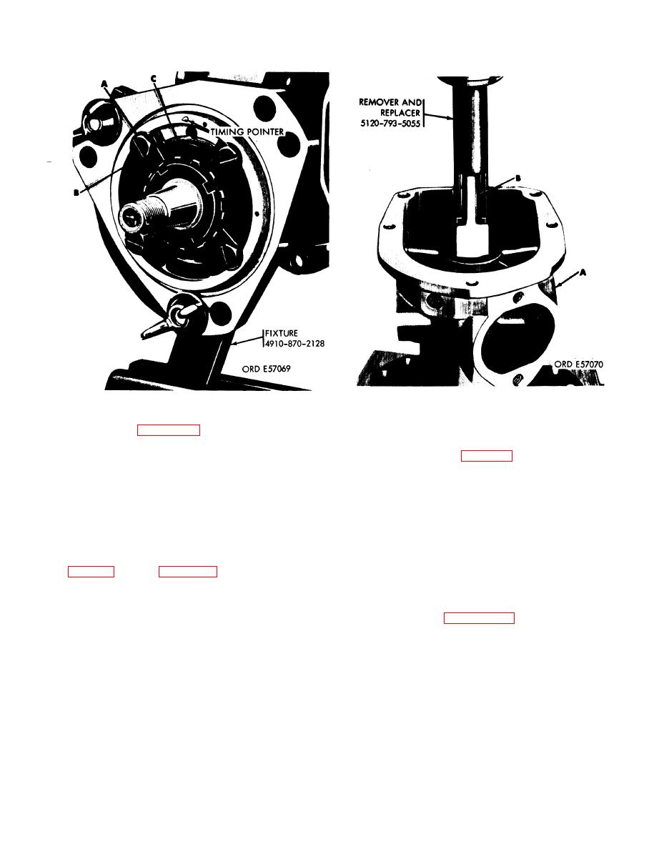
Figure 3-28. Pressing camshaft and associated parts from pump
Figure 3-27. Removing bearing retaining plate.
housing using remover and replacer 5120-793-5055.
Caution
(A) on bed of arbor press. Position remover and
Support the pump housing so that the
replacer on camshaft (B) and press the camshaft and
timing pointer (fig. 3-27) will not be
associated parts from the pump housing.
damaged.
Section Ill. REPAIR OF FUEL INJECTION PUMP COMPONENTS
indicated are the Army number, Federal stock
3-17. General. a. Parts Identification. Because of the
number, and the manufacturer's part number
numerous pump models repaired in this section of
(American-Bosch, FSCM 01843).
the manual a ready reference to parts is provided in
(3) Column 6, remarks. Defines differences in
parts shown in columns 2 through 6 for the par-
the pumps.
ticular part, indicates optional parts, and also shows
(1) Column 1, nomenclature. Defines pump and
parts available in kits.
part name.
(2) Columns 2 through 5. These columns list the
exploded views of the pumps and show the different
pumps as coded with the part number of the part
parts applications.
applicable to the particular pump. The numbers
3-11
|
|
Privacy Statement - Press Release - Copyright Information. - Contact Us |
